[820A]
[810A]
[810A]
[270]
PA unit
(PA ユニット)
[820B]
[810B]
[810B]
[300]
PA unit
(PA ユニット)
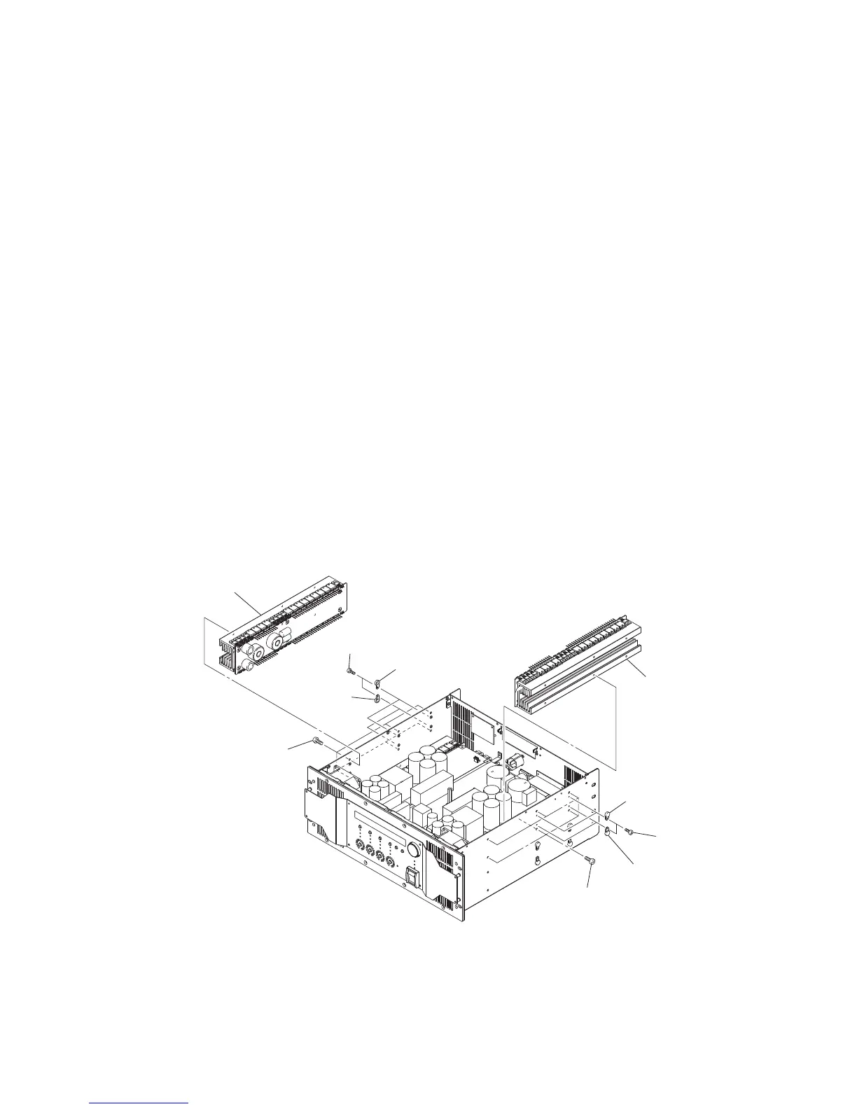
8. 上左側(CH1)PA ユニット(所要時間:約 15 分)
8-1. トップカバー、NX-DFLT カードを外します。
(1 項参照)
8-2. CONTROL シート、OPT アングルを外します。
(2 項参照)
8-3. 上左側の PA ユニットと他のユニットを接続している
束線を外します。(図 7)
8-4. [820A]のネジ 4 本を外し、[810A]のネジカバー 4
個を外します。(図 7)
8-5. [270]のネジ 6 本を外し、上左側の PA ユニットを
外します。(図 7)
9. 上右側(CH2)PA ユニット(所要時間:約 15 分)
9-1. トップカバー、NX-DFLT カードを外します。
(1 項参照)
9-2. CONTROL シート、OPT アングルを外します。
(2 項参照)
9-3. 上右側の PA ユニットと他のユニットを接続している
束線を外します。(図 7)
9-4. [820B]のネジ 4 本を外し、[810B]のネジカバー 4
個を外します。(図 7)
9-5. [300]のネジ 6 本を外し、上右側の PA ユニットを
外します。(図 7)
8. Upper left (CH1) PA unit
(Time required: about 15 minutes)
8-1. Remove the top cover and the NX-DFLT card.
(See procedure 1.)
8-2. Remove the CONTROL circuit board and the OPT
angle. (See procedure 2.)
8-3. Disconnect the connector assemblies which connects
the upper left PA unit and other units. (Fig. 7)
8-4. Remove the four (4) screws marked [820A], and
remove the four (4) screw covers marked [810A].
(Fig. 7)
8-5. Remove the six (6) screws marked [270]. The upper
left PA unit can then be removed. (Fig. 7)
9. Upper right (CH2) PA unit
(Time required: about 15 minutes)
9-1. Remove the top cover and the NX-DFLT card.
(See procedure 1.)
9-2. Remove the CONTROL circuit board and the OPT
angle. (See procedure 2.)
9-3. Disconnect the connector assemblies which connects
the upper right PA unit and other units. (Fig. 7)
9-4. Remove the four (4) screws marked [820B], and
remove the four (4) screw covers marked [810B].
(Fig. 7)
9-5. Remove the six (6) screws marked [300]. The upper
right PA unit can then be removed. (Fig. 7)
[270]: BIND HEAD TAPPING SCREW-B 4x8 MFZN2B3 (--)
B タイト+ BIND
[300]: BIND HEAD TAPPING SCREW-B 4x8 MFZN2B3 (--)
B タイト+ BIND
[810A]: SCREW COVER T5N (--)
ネジカバー
[810B]: SCREW COVER T5N (--)
ネジカバー
[820A]: BIND HEAD TAPPING SCREW-B 3x8 MFZN2B3 (--)
B タイト+ BIND
[820B]: BIND HEAD TAPPING SCREW-B 3x8 MFZN2B3 (--)
B タイト+ BIND
Fig. 7
(図 7)
NXAMP4x4
31
 Loading...