18. Power switch
(Time required: about 25 minutes)
18-1. Remove the top cover and the NX-DFLT card.
(See procedure 1.)
18-2. Remove the CONTROL circuit Board and the OPT
angle. (See procedure 2.)
18-3. Disconnect the power switch connector assembly from
to the PSANHA circuit board.
18-4. Remove the PSANHA circuit Board. (See procedure 3.)
18-5. Disconnect the power switch connector assembly from
the PSANHB circuit board. (Fig. 12)
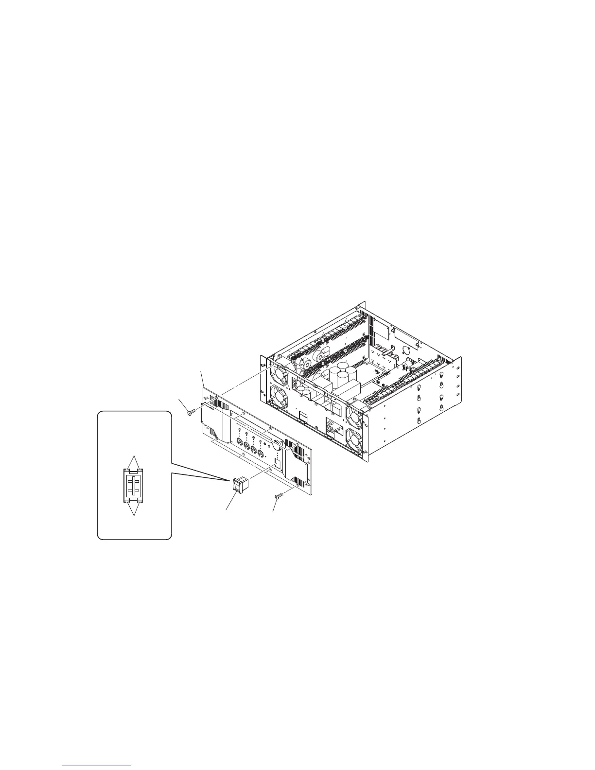
18-6. Remove the front panel assembly. (See procedure 12.)
18-7. Release the four (4) hooks of the power switch. The
power switch can be removed from the front panel
assembly. (Fig. 12)
18. 電源スイッチ(所要時間:約 25 分)
18-1. トップカバー、NX-DFLT カードを外します。
(1 項参照)
18-2. CONTROL シート、OPT アングルを外します。
(2 項参照)
18-3. PSANHA シートから電源スイッチ Ass'y の線材を外
します。(図 12)
18-4. PSANHA シートを外します。(3 項参照)
18-5. PSANHB シートから電源スイッチ Ass'y の線材を外
します。(図 12)
18-6. フロントパネル Ass'y を外します。(12 項参照)
18-7. 4 箇所のフックを解除し、フロントパネル Ass'y から
電源スイッチを外します。(図 12)
[660]
[660]
Front panel assembly
(フロントパネルAss'y)
Power switch
(電源スイッチ)
Power switch
(電源スイッチ)
HookHook
(フック)
Hook
(フック)
[660]: FLAT HEAD SCREW 4x8 MFZN2B3 (--)
小ネジ+ FLAT
Fig. 12
(図 12)
NXAMP4x4
36
 Loading...