1. Measurement Conditions
1-1. Environment
• Normal temperature: From 10 ˚C to 35 ˚C
• Normal humidity: From 45 % to 85 %
1-2. Power Source
• When measuring the electrical characteristics, set the power supply voltage and frequency as specified in the table
below.
1-3. Measuring Instruments
• Use a reliable measuring device capable of precisely measuring the specification values indicated in this document.
• Input impedance of the measuring instrument should be more than 1 MΩ.
• The noise level should be measured with a 22 Hz-22 kHz band pass filter.
When you use the Audio Analyzer System made by Audio Precision, Inc. for noise measurement, set the filter
characteristics as follows.
BW : 22 Hz-22 kHz
Filter (Fltr) : None
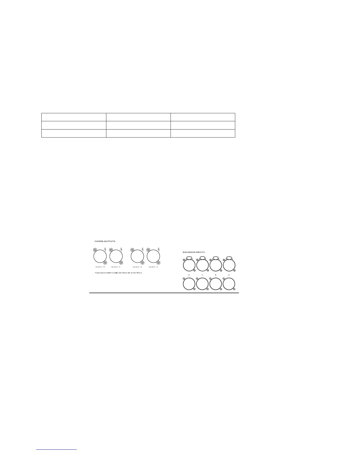
1-4. Connections
Each input and output terminal of channels 1-4 are as shown in the figure below.
1-4-1. Input connector
XLR-3-31 (female) type connectors are used for input terminals in channels 1-4.
Condition : Balanced input
Wiring : pin 1 to ground, pin 2 to hot (+), pin 3 to cold (-)
1-4-2. Output connector
Neutrik SPEAKON connectors are used for output terminals in channels 1-4.
Connect a load resistor between pin 1+ and pin 1- of the Neutrik SPEAKON connector.
1-4-3. Load resistor
Use a load resistor with no inductivity and a power rating high enough to perform each test safely.
1-4-4. Link out connectors
XLR-3-32 (male) type connectors are used for input terminals in channels 1-4.
Condition : Balanced output
Wiring : pin 1 to ground, pin 2 to hot (+), pin 3 to cold (-)
Fig. 1
■
INSPECTIONS
Destination Power supply voltage Frequency
U 120 V +2/-0 % 60 Hz
CHN 230 V +2/-0 % 50 Hz
Ch4
OUT
Ch3
OUT
Ch2
OUT
Ch1
OUT
Ch4
IN
Ch4
LINK
OUT
Ch3
LINK
OUT
Ch2
LINK
OUT
Ch1
LINK
OUT
Ch3
IN
Ch2
IN
Ch1
IN
NXAMP4x4
78
 Loading...