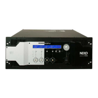
Fig. 20
(図 20)
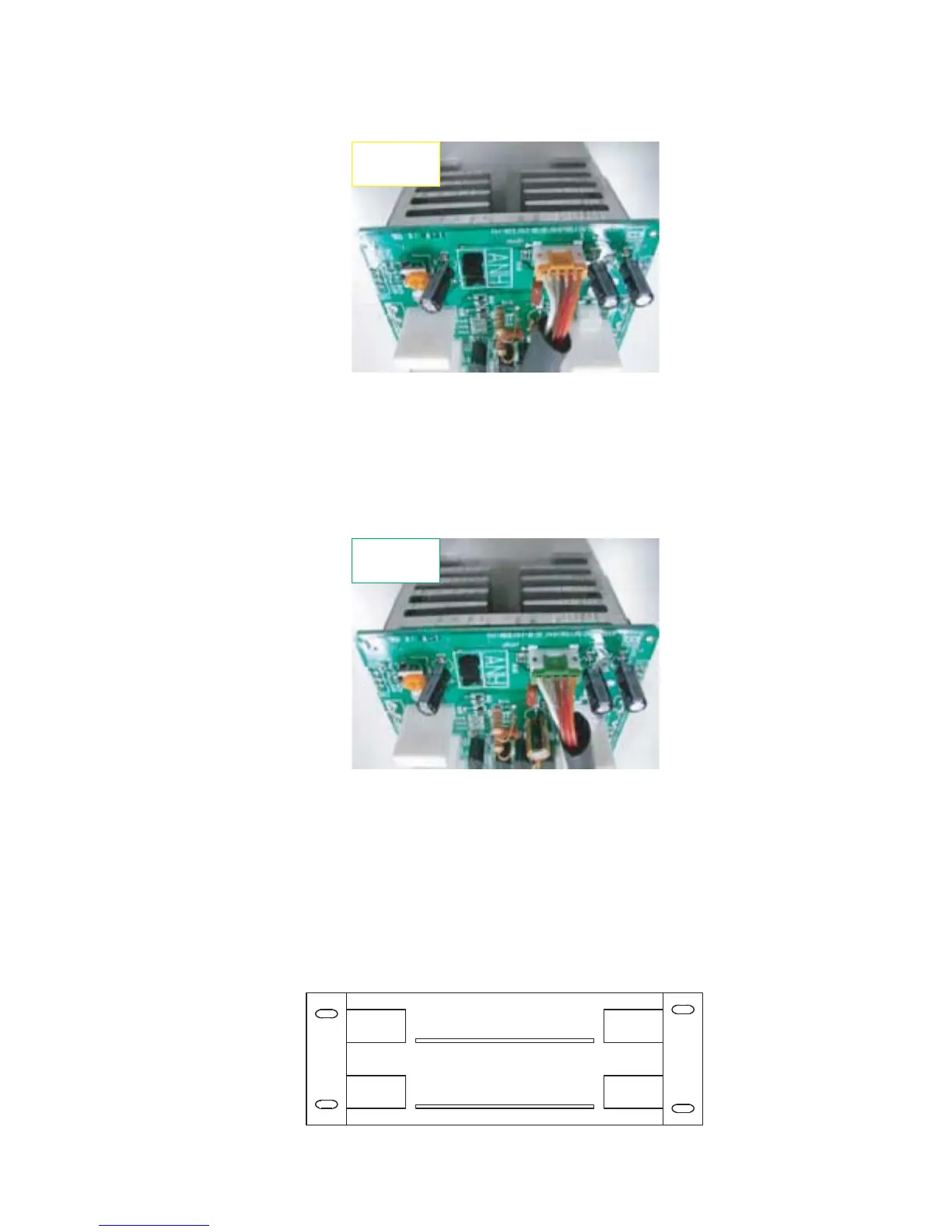
Fig. 21
(図 21)
NOTE: The wire to be connected is WK17110.
Install this PA unit on the lower right side of
enclosure.
Hereafter, this unit is called PA-UNIT of CH4.
注意: 線材(WK17110)を接続します。
この PA ユニットを筐体の下右側へ取り付け
ます。
これ以後、このユニットを CH4 の PA ユニッ
トと呼びます。
NOTE: The wire to be connected is WK17100.
Install this PA unit on the lower left side of
enclosure.
Hereafter, this unit is called PA unit of CH3.
注意: 線材(WK17100)を接続します。
この PA ユニットを筐体の下左側へ取り付け
ます。
これ以後、このユニットを CH3 の PA ユニッ
トと呼びます。
CN401
YELLOW (黄)
CN401
GREEN (緑)
* The following figure describes a layout drawing of
the PA units seen from the front panel. (Fig. 22)
※ 次の図は、フロントパネル側から見た PA ユニッ
トのレイアウト図です。(図 22)
CH1
RED
(赤)
CH3
YELLOW
(黄)
CH2
BLUE
(青)
CH4
GREEN
(緑)
PSANHA
PSANHB
Fig. 22
(図 22)
NXAMP4x4
13
 Loading...