OPT angle
(OPT アングル)
OPT angle
(OPT アングル)
[580][550] [550]
[560]
[555]
[530]
[580]
CONTROL
OPT-AN
OPT-AN
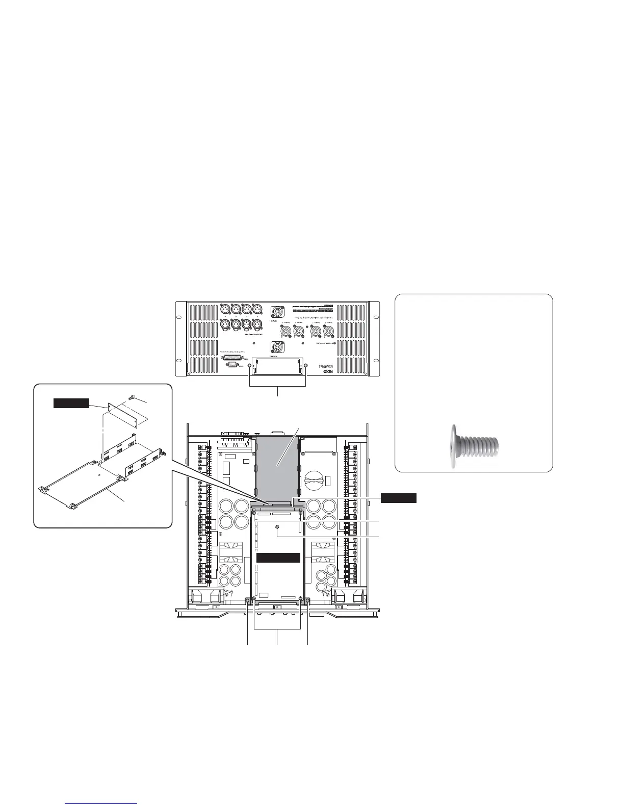
CAUTION
The figure below shows the screw
marked [555] head shape.
To avoid the unit malfunction, make sure
the screw marked [555] head shape is
same as shown below before
assembling the OPT angle.
[555]のネジ頭形状を下図に示します。
動作不良防止のため、OPT アングルを取り
付ける前に、[555]のネジ頭形状が下図のと
おりであることを確認してください。
2. CONTROL Circuit Board, OPT angle and OPT-
AN Circuit Board
(Time required: about 10 minutes)
2-1. Remove the top cover and the NX-DFLT card.
(See procedure 1.)
2-2. Disconnect the connector assemblies from the
CONTROL circuit board. (Fig. 2)
2-3. Remove the four (4) screws marked [580]. The
CONTROL circuit board can then be removed. (Fig. 2)
2-4. Remove the two (2) screws marked [550], one (1)
screw marked [555] and the two (2) screws marked
[560]. The OPT angle can then be removed together
with the OPT-AN circuit board. (Fig. 2)
2-5. Remove the two (2) screws marked [530]. The OPT-
AN circuit board and the OPT angle can then be
separated. (Fig. 2)
2. CONTROL シート、OPT アングル、OPT-AN シー
ト(所要時間:約 10 分)
2-1. トップカバー、NX-DFLT カードを外します。
(1 項参照)
2-2. CONTROL シートから束線を外します。(図 2)
2-3. [580]のネジ 4 本を外し、CONTROL シートを外し
ます。(図 2)
2-4. [550]のネジ 2 本、[555]のネジ 1 本、[560]のネ
ジ 2 本を外し、OPT アングルを OPT-AN シートと共
に外します。(図 2)
2-5. [530]のネジ 2 本を外し、OPT-AN シートと OPT
アングルを別けます。(図 2)
[530]: BIND HEAD TAPPING SCREW-S 3x6 MFZN2W3 (--)
S タイト+ BIND
[550]: BIND HEAD TAPPING SCREW-S 3x6 MFZN2W3 (--)
S タイト+ BIND
[555]: BIND HEAD TAPPING SCREW-S 3x6 MFZN2B3 (--)
S タイト+ BIND
[560]: BIND HEAD TAPPING SCREW-S 3x6 MFZN2B3 (--)
S タイト+ BIND
[580]: BIND HEAD TAPPING SCREW-S 3x6 MFZN2W3 (--)
S タイト+ BIND
Fig. 2
(図 2)
NXAMP4x4
26
 Loading...