Description of functions - Basic functions
35
FIGHTER 1330
A thermostat can be connected to temporarily change
the calculated flow temperature. It is also possible to
connect a thermostat to the sub shunt system (see the
section Description of functions - Expansion card 1 >
Sub shunt). When thermostat control is required, Ther-
mostat should be selected in the menu 9.1.11.
Alternatively a room sensor of the type RG10 (acces-
sory) can be connected to the system. This includes
settings for the required room temperature and the
system automatically compensates the calculated flow
temperature according to the difference between the
true and required room temperature.
Room sensors can be used together with the cooling
functions on Expansion card 2. Cooling production
starts at 1 degree excess temperature in the room
if, at the same time, the mean outside temperature
(menu 4.1) exceeds the set temperature in menu 6.4.5
alternatively 6.8.6.
Menu 9.1.11 Room control mode
Here the type of room control connected is set.
Selectable modes are Off, Thermostat, RG05 or
RG10. The factory setting is Off.
If Thermostat is selected in menu 9.1.11:
Menu 2.5 External adjustment
When the thermostat is selected in menu
9.1.11, you can connect an external contact,
see Electrical connection - External contacts.
Using an external contact, for example, a room
thermostat or a timer allows you to temporarily
or periodically raise or lower the flow tempera-
ture and with that the room temperature. When
the external contact is made, the heating curve
offset is changed by the number of steps
shown here. The value is adjustable between
-10 and +10. The factory setting is 0.
Even the menu 3.5 (External adjustment 2)
comes into question if the Sub shunt (SV-V2)
has been activated.
If RG10 or RG05 is selected in menu 9.1.11:
Menu 6.9.1 Room balancing
Here you set the factor that determines how
much deviation between the desired and true
room temperatures shall affect the flow tem-
perature. The factor is adjustable between 0
and 6 in increments of 0.1. The factory setting
is 1.0.
Menu 6.9.2 Room balancingsystem
Here you select which heating system the room
sensor shall affect. Can be set to Off, Heating
syst1, Heating syst2 or Heatingsys 1&2. The
factory setting is Off.
If RG10 or RG05 is selected in menu 9.1.11:
Menu 6.9.3 Desired room temperature
The menu is only displayed if RG05 is select-
ed in menu 9.1.11. The value can be adjusted
between 10 and 30 °C in increments of 0.5 °C.
Factory setting is 20 °C.
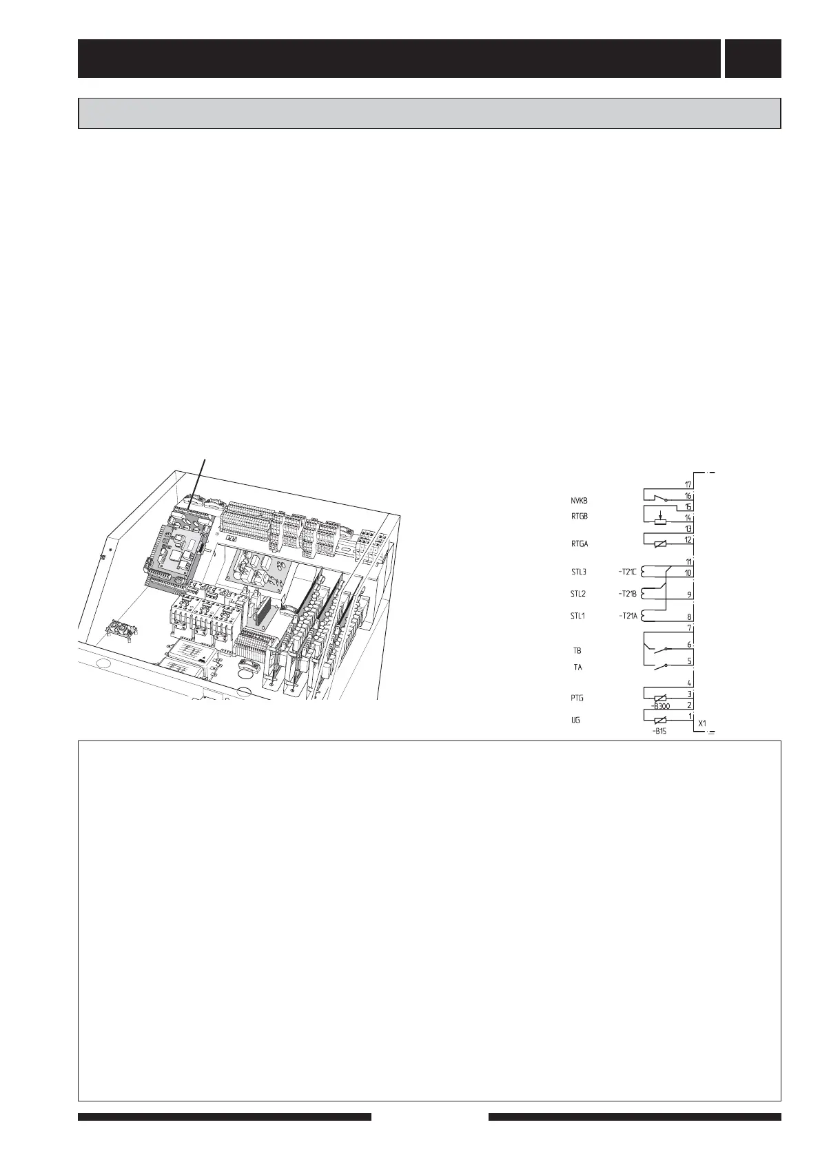
Connection of room control
When Thermostat is selected in menu 9.1.11:
Connect the thermostat for heating system 1 to
the screw terminals X1:12 and 13 on the EBV-
card (RTGA) and, when required, the thermostat
for heating system 2 (Sub shunt) to the terminal
blocks X1:14 and X1:15 on the EBV-card (RTGB).
The thermostat/s shall be potential free and nor-
mally open (NO).
If RG10 is selected in menu 9.1.11:
Connect screw terminal X1:12 to the screw termi-
nal in RG10 marked 2.
Connect screw terminal X1:13 to the screw termi-
nal in RG10 marked 6.
Connect screw terminal X1:14 to the screw termi-
nal in RG10 marked 1.
If ”RG05” is selected in menu 9.1.11:
Connect X1:12-13.
+EBV-card
LEK
X1
Room control
Quick guide - menu settings room control