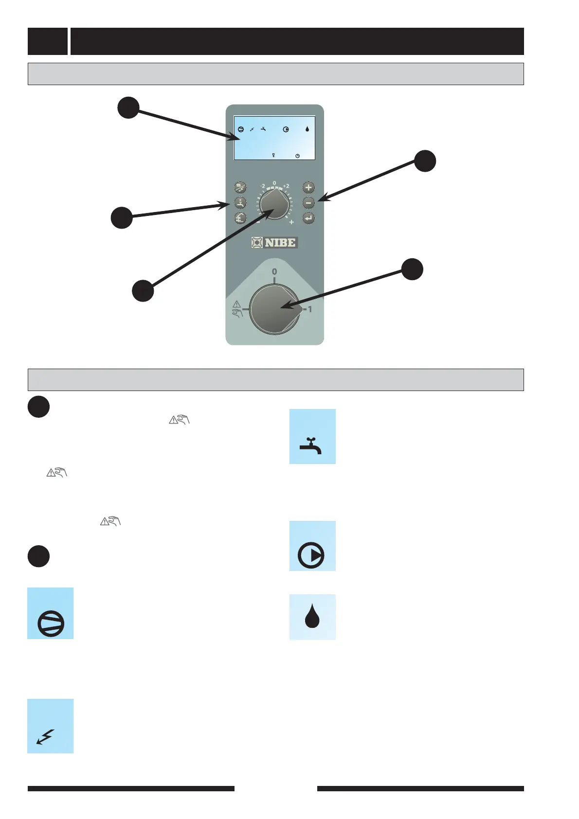
Front panel
FIGHTER 1330
4
A B I II
50.0 C
Hotwatertemperature
13.43
1.0
A B
Display
Switch
Left
keypad
Heating
curve offset
Layout
A
B
C
D
Right
keypad
E
Explanation
Switch
with three positions 1 - 0 - :
1 Normal mode. All control functions connect-
ed.
0 Heat pump off.
See the section, Description of functions -
Start up >Standby mode.
The power switch must not be turned to either
the “1” or “ ” position before the heating sys-
tem has been filled.
A
Display
First row:
Compressor symbol
Indicates that one of the compressors in
the heat pump is operational.
A indicates that compressor A (lower
module) is operational.
B indicates that compressor B (top mod-
ule) is operational.
Additional symbol
Indicates when immersion heater is opera-
tional.
B
I II III
A B
Extra hot water symbol
Indicates when the Extra hot water function
is active.
A indicates that a temporary temperature
increase is activated.
B indicates that a time determined tem-
perature increase, for example periodic,
is activated.
Circulation pump symbol
I indicates that the heating medium
pump A is operational.
II indicates that the heating medium
pump B is operational.
Oil boiler symbol
Indicates that the oil boiler is activated.
A B
I II
Second row: Value of the current parameter.
Third row: Description of current display param-
eter.
Fourth row: Shows menu numbers, key lock, clock
symbol and time.