Description of functions - Basic functions
FIGHTER 1330
24
The outdoor temperature (UG) and set value for heat
curve give a theoretical set point value, which the
building's heating system needs in order to heat the
house. The set point value as a function of the true
flow temperature (FG) gives a value in degree-minutes
as a basis for operation in heating mode.
The desired operating mode with regard to
permitting/blocking of the circulation pump and
additional heating is set using the Operating
mode button. The selection does not need to be
confirmed with the enter button.
The current operating mode is shown on the display
when the button is pressed and the mode changes
when you continue to press the button. The display
returns to the normal display mode once the enter but-
ton is pressed.
The different operating modes are:
Auto mode:
FIGHTER 1330 automatically selects the operating
mode by taking the outdoor temperature into account.
The circulation pumps and additional heating are per-
mitted to be operational when the need arises.
Summer mode:
Only hot water production using FIGHTER 1330. The
circulation pumps and additional heating are blocked.
However, when Extra hot water is activated the addi-
tional heat (XVV) can be connected.
Spring/Autumn mode:
Only production of heating and hot water using FIGHT-
ER 1330. The circulation pumps are operational. Addi-
tional heat blocked. However, when Extra hot water is
activated the additional heat (XVV) can be connected.
Only additional heat:
Compressors blocked. The function can also be acti-
vated/deactivated by pressing the “operating mode
button” for 7 seconds.
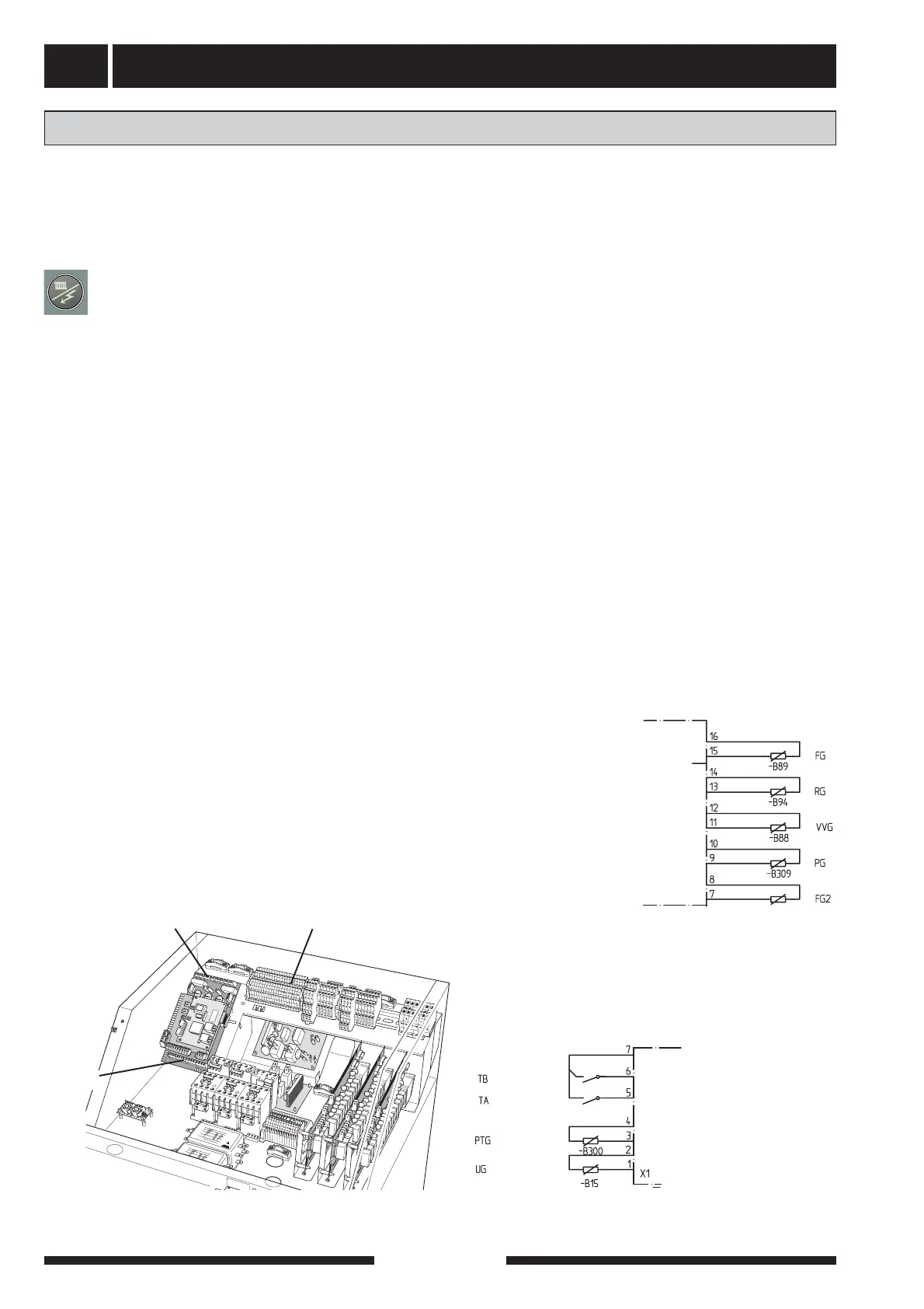
Connection of heat production
The flow temperature sensor (FG) is installed on the
flow line towards the heating system. For a more exact
placement see each docking option. The sensor must
make good contact with the measurement area to
give the best function. When a submerged tube is not
available, use the supplied copper tube. The sensor is
connected to screw terminals X4:15 and X4:16 on the
EBV-card.
The return line temperature sensor (RG) is installed
on the return line from the heating system. For a more
exact placement see the selected docking option. The
sensor must make good contact with the measurement
area to give the best function. When a submerged
tube is not available, use the supplied copper tube.
The sensor is connected to screw terminals X4:13 and
X4:14 on the EBV-card.
The outside sensor (UG) must be installed in a shaded
location on a wall facing north or north-west, where it
will not be affected by any morning sun. The sensor
is connected using a two-core cable to the terminal
blocks X1:1 and X1:2 on the EBV-card.
The external heating medium pump's (VBP3) con-
trol signal is connected to the terminal block X6:19
(230 V), X6:20 (N) (max 0.2 A) on the EBV-card.
Note that FIGHTER 1330 delivers 230 V control sig-
nals intended to control external contactors and
not to drive pumps.
LEK
X6
X1
X4
Heating
+EBV-card
X4
+EBV-card