Description of functions – Expansion card 2
FIGHTER 1330
48
LEK
The installation consists of one or more FIGHTER
1330s with accumulator tanks on both the collector
and heat medium sides. Ground/rock collector(s) have
three way valves so that the accumulator tanks can be
utilised as:
1. Heat storage in heating mode
2. Cold storage in passive cooling mode
3. Heat dump in active cooling mode
Heat production occurs via the accumulator tank
where the flow line sensor (FG) is located.
The circulation pump (VBP3) circulates the heating
medium from the tank to the distribution system.
The brine circulates between the brine tank and the
heat pump evaporator. When the temperature is low-
ered in the tank (small cooling requirement in the
system) the circulation pump (CP-KO) is started to
retrieve energy from the collector.
When the cooling sensor (KG) requests cooling, the
circulation pump (CP-K) starts and the shunt valve
(SV-K) starts regulating cooling from the brine tank. In
the event of falling temperatures in the tank (KBack)
CP-KO is started to retrieve cooling from the collec-
tor (passive cooling). When the collector is unable to
provide sufficient cooling the heat pump is started to
produce active cooling.
In the event of excess heat, this is dumped to the col-
lector or outdoor air via a fan battery outdoors.
Connecting cooling/heating modes with
accumulators
NOTE! When dumping the excess heat in the
outdoor air, the circulation pumps for dumping
(CP-D) must be connected in parallel. The fans in the
outdoor air module can also be connected with CP-D.
VXV-KV A/B must not be used.
Three way valve (VXV-KV A/B) is connected to termi-
nal block X6B:1 (230 V), X6B:2 (N) and X6B:3 (NC)
alternatively X6B:4 (NO).
The control valve (SV-VVX) is connected to terminal
block X6B:8 (230 V reduce signal), X6B:9 (N) and
X6B:10 (230 V increase signal).
There are three potential free relays for functions CP-D,
CP-KO & CP-K, which can be used as control voltage
or power supply (Max 6 A, 250 V). If the relay is used
as control voltage the supply can be bridged internally
from X13:4 to X6B:18, , X6B:20 and X6B:22 and use
X13:9 as N and receive the control signal for CP-D
on X6B:19, CP-KO on X6B:21 and CP-K on X6B:23.
When connected like this the max current must be 1 A
from X13:4 and the control voltage is 230 V.
External supply to the control signal/power supply for
CP-D is connected to terminal block X6B:18 (max fus-
ing 6 A and 250 V) and the control signal/power supply
is on X6B:19.
External supply to the control signal/power supply for
CP-KO is connected to terminal block X6B:20 (max
fusing 6 A and 250 V) and the control signal/power
supply is on X6B:21.
External supply to the control signal/power supply for
CP-K is connected to terminal block X6B:22 (max fus-
ing 6 A and 250 V) and the control signal/power supply
is on X6B:23.
The sensors must have a good contact with the meas-
uring point for best function. If a submerged tube is not
available, use the copper tube supplied.
For the cooling sensor (KG) location see docking
instructions. The sensor is connected to screw termi-
nals J5:7 and J5:8 on the “measurement card”.
For the sensor KB-KO location see docking instruc-
tions. The sensor is connected to screw terminals
J4:21 and J4:22 on the “measurement card”.
For the cooling sensor (KBack) location see docking
instructions. If a submerged tube is not available, use
the copper tube supplied. The sensor is connected to
screw terminals J4:23 and J4:24 on the “measurement
card”.
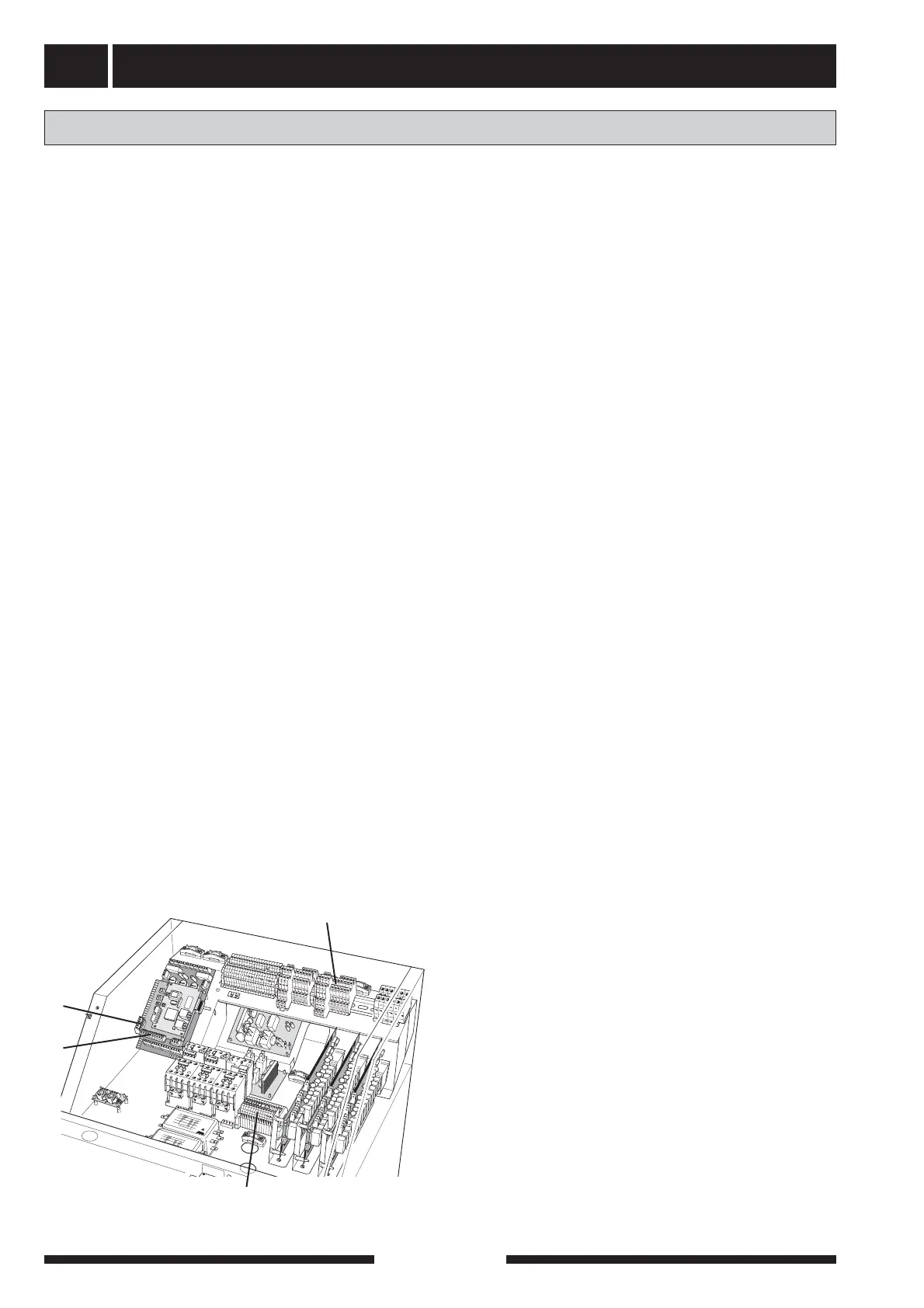
J5
J4
X6B
X13
Combined cooling/heating modes with accumulators
The outline diagram with docking instruc-
tions is available at www.nibe.com