Actions with operating disturbances
FIGHTER 1330
80
High condenser return
The temperature on the incoming heating medium
(VBRA or VBRB) is higher than maximum temperature
in menu 5.4.1.
This may be due to:
■ Too high flow on the heating medium.
■ Too high stop temperature for hot water charging,
check menu 1.2.
The alarm is reset when the temperature drops by 2
degrees below the set max temperature.
Hi Brinealarm
Incoming brine temperature (KBinA) exceeds the
value set in menu 5.4.3.
The alarm is reset when the temperature drops by 2
degrees below the set temperature.
Lowbrinealarm
The temperature on the outgoing brine pump (KButA
or KButB) is lower than the value set in menu 5.4.2.
This may be due to:
■ Too low flow on the brine.
The alarm is reset when the temperature increases by
2 degrees above the set temperature.
Hot gas-alarm
Occurs when the hot gas sensor (HGA or HGB) tem-
perature exceeds 135 °C.
This may be due to:
■ Defective/incorrect setting on the expansion valve
The alarm is reset when the temperature drops below
90 °C. Becomes continuous after three repetitions
within 240 minutes.
Com. error
Occurs when communication with one of the units
fails.
This may be due to:
■ Broken cable between heat pumps.
■ Incorrect Master/Slave setting. See the section
Description of functions - Start up > Master / Slave.
The alarm is reset automatically within 10 minutes
from when the cause of the fault was rectified.
High condenser flow
The temperature of the outgoing heating medium
(VBFA or VBFB) is outside the compressor's working
range.
This may be due to:
■ Incorrect flow.
■ Incorrect settings
The alarm is reset when the temperature drops
2 degrees on the return line.
In the event of an alarm the background lighting
flashes and the alarm is presented in plain text on the
affected heat pump if the screen saver is active. The
alarm status is also shown in menu 0.1.x and 5.2.0 as
well as 5.3.0. If a constant alarm occurs this is saved
in the alarm log together with numerous temperatures
and output statuses (menu 9.3.0).
All alarms stop the compressor affected by the fault.
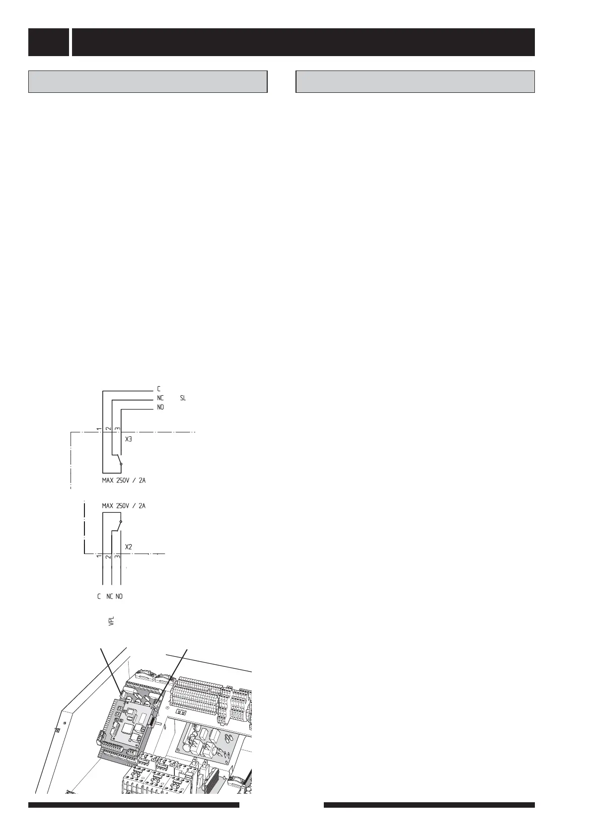
In the event of a constant alarm, the heat pump alarm
relay is activated (VPL) on the affected heat pump. A
common alarm is also activated on the Master when
alarm occurs on any of the heat pumps in the system
(SL).
Both relays are potential free and may be loaded max.
with 250 V and 2 A. The relays are drawn in the alarm
positions on the wiring diagram.
The heat pump alarm (VPL) is connected to the termi-
nal blocks X2:1 (signal feed), X2:2 (NC in the event of
an alarm), X2:3 (NO in the event of an alarm) on the
EBV-card.
Common alarm (SL) is connected to the terminal
blocks X3:1 (signal fed), X3:2 (NC in the event of an
alarm) and X3:3 (NO in the event of an alarm) on the
EBV-card.
Alarm
Alarm with automatic resetting
X2
X3
+EBV-card
+EBV-card