Pipe connections
FIGHTER 360P
12
Pipe installation must be carried out in accordance
with current norms and directives.
The system requires a low-temperature design of the
radiator circuit. At DUT, the highest recommended
temperatures are 55 °C on the supply line and 45 °C
on the return line.
When the circulation pump is running, the flow in the
radiator circuit must not be completely stopped. In oth-
er words, in a system where the radiator flow might
stop because all thermostat valves are closed, there
must be a bypass valve to protect the circulation
pump.
The total volume is 240 litres, with 170 litres in the
water heater and 70 litres in the double-jacket space.
The pressure vessel in the FIGHTER 360P is approved
for max 9.0 bar (0.9 MPa) in the water heater and
2.5 bar (0.25 MPa) in the double jacket space.
Overflow water from the evaporator collection tray and
safety valves goes via non-pressurised collecting
pipes to a drain so that hot water splashes cannot
cause injury.
Other heat sources can be docked to the FIGHTER
360P Accessories are needed. Contact NIBE AB for
information.
General
Docking
NOTE!
The pipe work must be flushed
before the heat pump is connected,
so that any contaminants do not
damage the component parts.
For the Installer
To empty the water heater proceed as follows:
■ Disconnect the overflow pipe from the drain con-
nection (79) and connect a hose to a draining
pump instead. Where no draining pump is availa-
ble, the water can be released into the overflow
funnel (99).
■ Open the safety valve (47).
■ Open a hot water tap to let air into the system. If
this is not enough, undo a pipe coupling (74) on
the hot water side and pull out the pipe.
Emptying the water heater
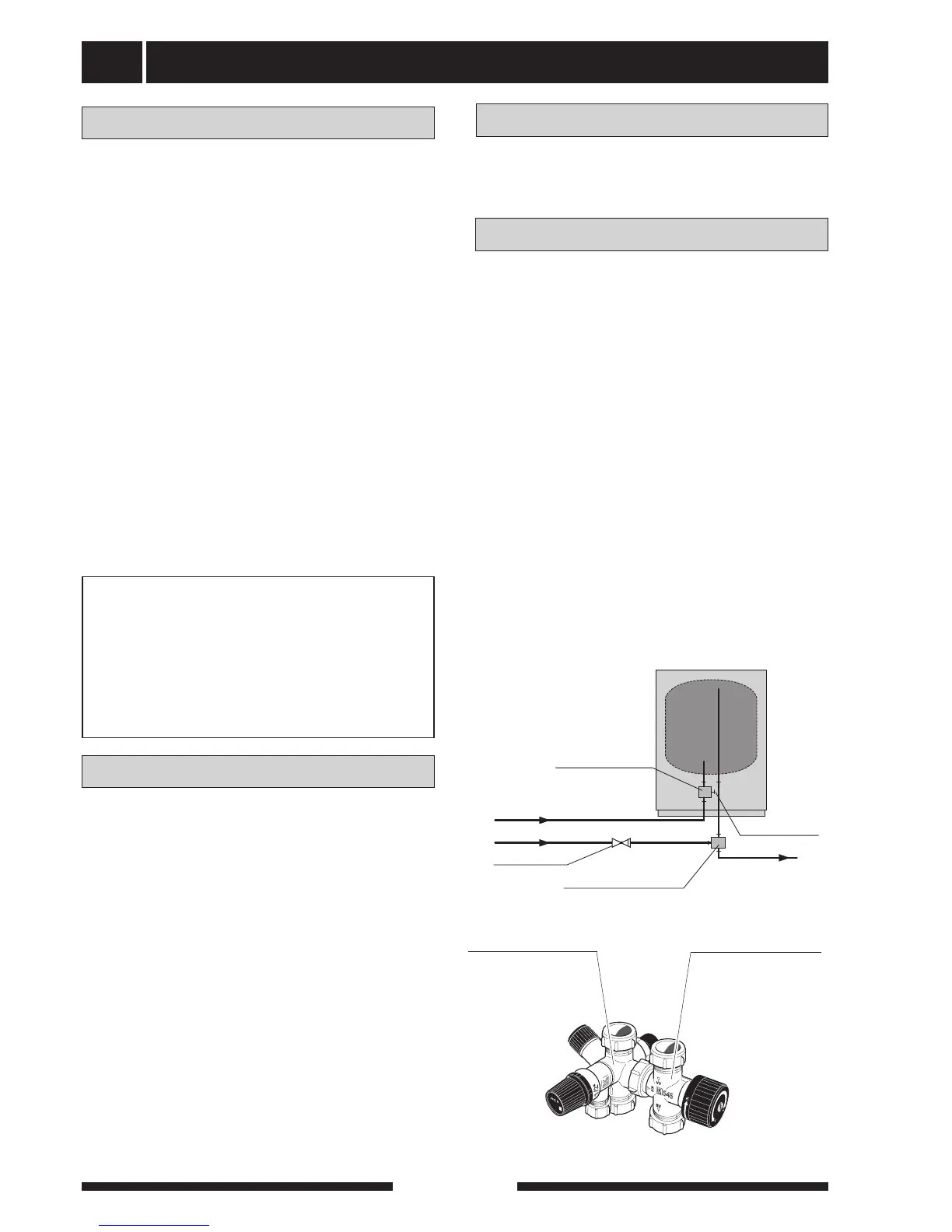
Tap water connection
Hot and cold water are connected to pos (74) (hot
water) and (73) (cold water).
The attendant expansion vessel (107) must be con-
nected to the hot water system.
The heat pump should be supplemented with an elec-
tric water heater if a bubble pool or other significant
consumer of hot water is installed.
If the heater is equipped with a valve connection Ø of
15 mm, this should be replaced with an equivalent
(split) Ø 22 mm coupling.
Appropriate heaters are COMPACT 100-300 for floor-
mounting and EMINENT 35-100 for wall-mounting.
1. Split the valve coupling.
2. Attach the valve coupling section to the heater’s
incoming cold water.
3. Attach the mixing valve section to the heater’s out-
going hot water.
4. Plug the split on the valve coupling section.