Ventilation connection
FIGHTER 360P
For the Installer
14
FIGHTER 360P is connected so that all ventilation air
except the kitchen fan passes the evaporator (62) in
the heat pump. The lowest ventilation flow according
to current standards is 0.35 l/s per m
2
floor area. For
optimum heat pump performance the ventilation flow
should not be less than 110 m
3
/h. (31 l/s).
The heat pump's installation area should be ventilated
by at least 36 m
3
/h (10 l/s).
FIGHTER 360P is equipped with a ventilation
opening in the base. As a result, an air flow of about 5
m
3
/h (1,4 l/s) is taken directly from the room where the
heat pump is installed.
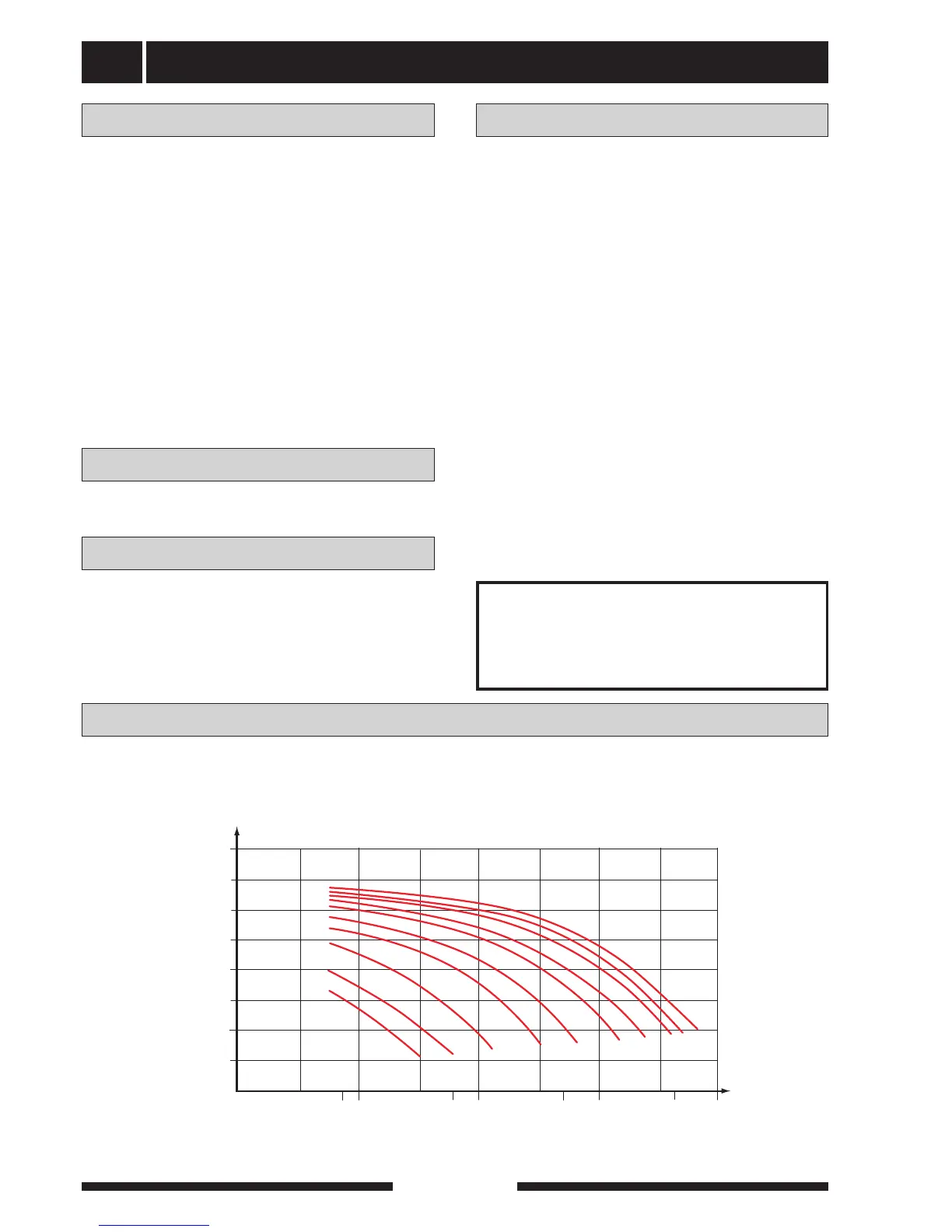
Changing the ventilation capacity is described under
Electrical connection - Setting the fan capacity. See
also Circuit diagram. The numbering of the curves
refers to the numbering on the fan terminal block (22).
To obtain the necessary air exchange in every room of
the house, the exhaust air devices must be correctly
positioned and adjusted. A defective ventilation instal-
lation may lead to reduced heat pump efficiency and
thus poorer operating economy, and may result in
damage to the house.
NOTE!
A duct in a masonry chimney stack
must not be used for extract air.
To prevent fan noise being transferred to the exhaust
air devices, it may be a good idea to install a silencer
in the duct. This is especially important if there are
exhaust air devices in bedrooms.
As the heat pump contains a flammable refrigerant in
the form of propane (R290), the air ducting system
must be earthed. This is done by making a sound elec-
trical connection to the exhaust air and vented air
ducts with the two earthing cables supplied. The cables
must then be connected to the earthing studs on top
of the top cover.
Connections should be made via flexible hoses, which
must be installed so that they are easy to replace. The
extract air duct must be provided with diffusion-tight
insulation over its entire length. Provision must be
made for inspection of the duct. Make sure that there
are no reductions of cross-sectional area in the form
of creases, tight bends etc, since this will reduce the
ventilation capacity. All joins in the ducting must be
sealed and pop-riveted to prevent leakage.
The air duct system should, at a minimum, be of air
tightness class B.
The diagram below shows the available ventilation
capacity.
Fan diagram
Ventilation flow Duct installation
Adjustment