EasyManua.ls Logo

Nibe FIGHTER 360P - Electrical Wiring and Connections

Nibe FIGHTER 360P
60 pages
Print Icon
To Next Page IconTo Next Page
To Previous Page IconTo Previous Page
Loading...
Electrical connection
15
For the Installer
FIGHTER 360P
FIGHTER 360P must be installed via an isolator
switch. Other electrical equipment, except the outdoor
sensor and the current sensors, are connected at the
factory.
Disconnect the heat pump before insulation testing
the house wiring.
FIGHTER 360P can be connected to a single phase
power suppply.
The connection is made according to the illustrations
below depending on the desired maximum output.
Max phase current, single phase
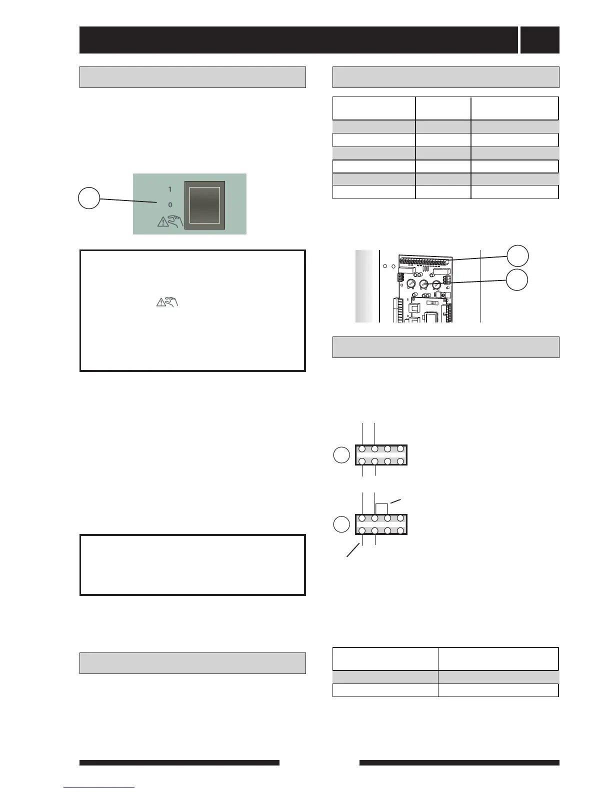
The knob (101) should always be set to position D
when using a single phase power supply.
The two immersion heaters have a total maximum out-
put of 13.5 kW. The power rating as set at the factory
is 7.5 kW, which corresponds to position C on the knob
(101) on the load monitor card (2).
Connection
Single phase connection
Output as set at the factory
NOTE!
Reset the temperature limiter,
it may have tripped during transport.
NOTE!
The switch (8) must not be moved
from 1 or “ ” until the boiler has
been filled with water. Otherwise the
temperature limiter, thermostat,
compressor and the immersion heater
can be damaged.
The automatic heating control system, circulation
pump (16) and its cabling, are internally fuse protected
with a miniature circuit breaker (7).
The supply to the heat pump is connected to termi-
nal (9) via a strain relief. Connection must not be car-
ried out without the permission of the electricity sup-
plier and under the supervision of a qualified electri-
cian. The cable entry conduit is dimensioned for cable
with a max Ø 19 mm.
The power is controlled via a contactor which is oper-
ated by a microprocessor.
The temperature limiter (6) cuts off the supply to the
immersion heater if the temperature rises to between
90 and 100 °C; it can be manually reset by pressing
the button on the temperature limiter.
2
1
bar
3
04
A BA BA BI II III I II I II
54.1°C
Varmvattentemp.
1.0
13.43
8
Max phase current
011007
011007
011007
011007
A
r
t.nr
.
611827
2
1
bar
3
0
4
A r
t.nr
.
611827
2
1
bar
3
0
4
A
r
t.nr
.
611
82
7
2
1
bar
3
0 4
?
Här är pluggen (61)
bortskruvad. Används i
MAV Extra shunt.
LEK
LEK
LEK
LEK
The setting of the different max outputs is done using
the knob (101) on the load monitor card (2).
7,5 C 15,8
10,5 E 20,2
3,0 A 9,3
Immersion heater, Knob position Max load phase (A)
output (kW)
6,0 B 13,7
9,0 D 18,0
13,5 F 24,5
101
2
LP
HP
9
Inkommande matning 3 x 400 V
30
29
29
30
29
30
34
34
21
steg 2
steg 1
16
14
34
16
14
11
Re1
X29
4
X29
5
N
X29
6
29
11
Re1
X29
4
X29
5
N
X29
6
29
1
2
3
4
5
6
7
8
L2 L3 N L1
1
2
3
4
5
6
7
8
1
2
3
4
5
6
7
8
NO O/C
NO O/C
Tillsats Stillestånd
NC
NC
NO
O/C
NC
Hjälpkontaktor
(ingår ej vid leverans)
12 – 230V
15
88
90
86
41
33
3 4 1 2
5 6
89
93
29
30
29
30
29
30
16
14
34
NO O/C
NO O/C
NC
NC
16
14
34
34
3 4 1 2
5 6
91
9
Inkommande matning 3 x 230 V
L2 L3 N L1
9
Inkommande matning 1 x 230 V
L2 L3 N L1
29
30
29
30
1
8
7
6
5
4
3
2
EXTERNT
Start tillsatsvärme
Incoming supply 1 x 230V
Max output immersion heater 3 kW.
LP
HP
9
Inkommande matning 3 x 400 V
30
29
29
30
29
30
34
34
21
steg 2
steg 1
16
14
34
16
14
11
Re1
X29
4
X29
5
N
X29
6
29
11
Re1
X29
4
X29
5
N
X29
6
29
1
2
3
4
5
6
7
8
L2 L3 N L1
1
2
3
4
5
6
7
8
1
2
3
4
5
6
7
8
NO O/C
NO O/C
Tillsats Stillestånd
NC
NC
NO
O/C
NC
Hjälpkontaktor
(ingår ej vid leverans)
12 – 230V
15
88
90
86
41
33
3 4 1 2
5 6
89
93
29
30
29
30
29
30
16
14
34
NO O/C
NO O/C
NC
NC
16
14
34
34
3 4 1 2
5 6
91
9
Inkommande matning 3 x 230 V
L2 L3 N L1
9
Inkommande matning 1 x 230 V
L2 L3 N L1
29
30
29
30
1
8
7
6
5
4
3
2
EXTERNT
Start tillsatsvärme
Incoming supply 1 x 230V
Max output immersion heater 6 kW.
Supplied strap is connected
between L1 and L2.
Existing zero conductor is replaced
with the supplied zero conductor.
3,0 18,0
Immersion heater, Max total load phase (A)
output (kW)
6,0 31,3
strap
new conductor

Table of Contents

Related product manuals