Commissioning and adjusting
21
FIGHTER 360P
For the Installer
Air is initially released from the hot water and venting
may be necessary. If bubbling sounds can be heard
from the heat pump, the entire system requires further
venting. NOTE! Safety valve (52) also acts as a man-
ual venting valve. Operate it with care, since it opens
quickly. When the system is stable (correct pressure
and all air eliminated) the automatic heating control
system can be set as required. See the section Room
temperature - Setting the Automatic heating control
system and Front panel.
Readjustment
The ventilation flow and correct outlet on the fan termi-
nal block (22) are set out on the ventilation drawing.
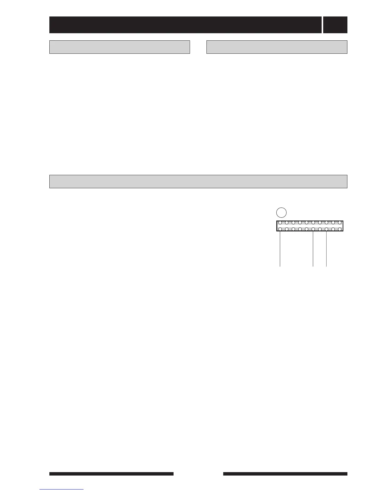
■ Change the fan capacity by moving the grey cable
on the fan terminal block (22) if necessary. Use the
lowest possible output to obtain the lowest noise
levels.
■Make sure that all outdoor air devices are fully open.
■ Set correct ventilation flows on the exhaust air
devices.
Now move the white and brown cables to obtain the
required exhaust air flow for fan speeds I and II. The
white cable corresponds to position I and the brown
position II. Note however that the exhaust air flow must
never fall below 110 m
3
/h (31 l/s).
Setting the ventilation
The ventilation capacity is selected by moving the
brown, grey and white cables to an appropriate outlet
on the terminal block (22). See the section, Ventilation
connection - Fan diagram to choose appropriate con-
nections.
The grey cable corresponds to the fan speed in nor-
mal mode. The white cable corresponds to speed I.
The brown cable corresponds to speed II.
Example:
Normal: Lowest possible fan speed is chosen to
obtain the planned ventilation flow (grey
cable).
Speed II:
Highest possible fan speed is chosen,
(forced)
however
consider ventilation noise (brown
cable).
Speed I Lowest possible fan speed is chosen
(reducing) where the min flow is maintained (white
cable).
Outlet Voltage (V)
1 100
2 110
3 125
4 140
5 155
6 170
7 185
8 200
9 215
10 230
Setting the fan capacity