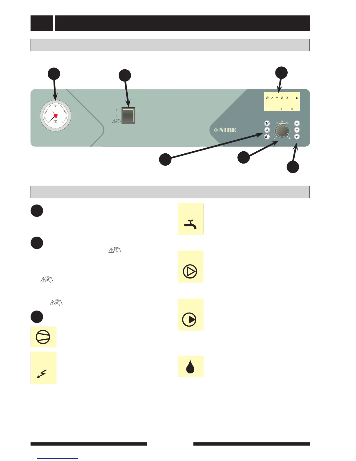
EasyManua.ls Logo

Nibe FIGHTER 360P - Front Panel Interface

Nibe FIGHTER 360P
60 pages
To Next Page IconTo Next Page
To Previous Page IconTo Previous Page
Loading...
Front panel
FIGHTER 360P
For Home Owners
4
Pressure gauge
The radiator circuit pressure is displayed here.
Gauge graduation is 0 - 4 bar. Normal pressure
is 0.5 1.5 bar.
Display
Art.nr . 511071
2
1
bar
3
04
A BA BI II IIII II I II
54.1 C
T e mp. VV-givare
1.0
13.43
Switch
Pressure gauge
A
B
C
Left
keypad
Heating
curve offset
Switch
with three positions 1 - 0 -
1 Normal mode. All control functions connect-
ed.
0 Heat pump off.
Standby. This position is used in the event of
operating disturbances.
Display First row:
Layout
Explanation
A
C
B
D
E
Right
keypad
F
2
1
bar
3
0 4
T
G
+2
0
-2
1
R
0
A B A B A BI II III I II I II
29,0
95,0 8,5
55,0
69,1
81,4
82,8
93,7
110,0
28,5
56,0
83,5
473,0
525,0
339,0
Hål 29x23
Hål 66x36
7 st hål Ø10,5
10,5
Ø 52,8
53,5
Urstansning
7 mm bred, r=3,5
2
1
bar
3
0 4
T
G
+2
0
-2
1
R
0
A B A B A BI II III I II I II
29,0
95,0 8,5
55,0
69,1
81,4
82,8
93,7
110,0
28,5
56,0
83,5
473,0
525,0
339,0
Hål 29x23
Hål 66x36
7 st hål Ø10,5
10,5
Ø 52,8
53,5
Urstansning
7 mm bred, r=3,5
2
1
bar
3
0 4
T
G
+2
0
-2
1
R
0
A B A B A BI II III I II I II
29,0
95,0 8,5
55,0
69,1
81,4
82,8
93,7
110,0
28,5
56,0
83,5
473,0
525,0
339,0
Hål 29x23
Hål 66x36
7 st hål Ø10,5
10,5
Ø 52,8
53,5
Urstansning
7 mm bred, r=3,5
2
1
bar
3
0 4
T
G
+2
0
-2
1
R
0
A B A B A BI II III I II I II
29,0
95,0 8,5
55,0
69,1
81,4
82,8
93,7
110,0
28,5
56,0
83,5
473,0
525,0
339,0
Hål 29x23
Hål 66x36
7 st hål Ø10,5
10,5
Ø 52,8
53,5
Urstansning
7 mm bred, r=3,5
2
1
bar
3
0 4
T
G
+2
0
-2
1
R
0
A B A B A BI II III I II I II
29,0
95,0 8,5
55,0
69,1
81,4
82,8
93,7
110,0
28,5
56,0
83,5
473,0
525,0
339,0
Hål 29x23
Hål 66x36
7 st hål Ø10,5
10,5
Ø 52,8
53,5
Urstansning
7 mm bred, r=3,5
Compressor symbol.
Indicates when the compressor is opera-
tional.
The switch must not be turned to 1 or
“ ” before filling the boiler with water.
Supplement symbol
Displayed when supplementary energy is
connected, usually the immersion heater.
The line indicates which power step/steps
are currently connected.
If the lightning symbol flashes, the power
output is limited by the load monitor.
I 3 kW supplementary power is connected
(1 or 2 kW for single phase installation)
II 4,5 kW supplementary power is connected
(0 kW for single phase installation)
III 6 kW supplementary power is connected
(2 or 4 kW for single phase installation)
Hot water symbol.
Indicates when the Extra hot water func-
tion is activated. A is shown when tempo-
rary selected temperature increase is acti-
vated and B when periodic temperature
increase is activated.
Fan symbol.
Indicates when the fan is operational.
Normal speed is indicated by just the fan
symbol. When one line is visible fan
speed I is activated and when two lines
are visible fan speed II is activated.
Heating system symbol.
Indicates when the house is being heat-
ed, i.e. the circulation pump is operation-
al. When the heat pump is connected to
two heating systems, I is shown for circu-
lation pump 1 and II for circulation pump
2.
2
1
bar
3
0 4
T
G
+2
0
-2
1
R
0
A B A B A BI II III I II I II
29,0
95,0 8,5
55,0
69,1
81,4
82,8
93,7
110,0
28,5
56,0
83,5
473,0
525,0
339,0
Hål 29x23
Hål 66x36
7 st hål Ø10,5
10,5
Ø 52,8
53,5
Urstansning
7 mm bred, r=3,5
Defrosting symbol
Indicates when evaporator defrosting is in
progress.
Value of the current parameter.
Second row:
Description of current display parame-
ter. Normally shows the Hot water tem-
perature
Third row:
Temp HW-sensor

Table of Contents

Related product manuals