English – 1
ENGLISH
Safety warnings
• IMPORTANT! – This manual contains important instructions and warn-
ings for personal safety. Incorrect installation could cause serious physical
injury. Read all parts of the manual carefully before starting work. If in doubt,
interruptinstallationandcontacttheNiceServiceCentreforclarications.
• IMPORTANT! – Important instructions: keep this manual in a safe place
to enable future product maintenance and disposal procedures.
Installation warnings
• Before commencing installation, check that the product is suitable for the
intended kind of use (see paragraph 2.2 “Limits of use” and chapter “Product
technicalspecications”).Ifnotsuitable,doNOTproceedwithinstallation.
• During installation, handle the product with care, avoiding the risk of crush-
ing, impact, dropping or contact with any type of liquid. Never place the
productnearsourcesofheatorexposetonakedames.Thismaydamage
productcomponentsandcausemalfunctions,reorhazardoussituations.If
this oc curs, suspend installation immediately and contact the Nice Service
Centre.
•Nevermakemodicationstoanypartoftheproduct.Operationsotherthan
asspeciedcanonlycausemalfunctions.Themanufacturerdeclinesallliabil-
ityfordamagecausedbymakeshiftmodicationstotheproduct.
•Theproductshouldnotbeusedbychildrenorpeoplewithimpairedphysical,
sensorial or mental capacities or who have not received adequate training in
the safe use of the product.
•Onthepowerlinetothesystem,installadevicefordisconnectionfromthe
power mains with a gap between contacts that assures complete disconnec-
tion in the conditions of overvoltage category III.
• Connect the control unit to an electric power line equipped with an earthing
system.
•Theproduct’spackagingmaterialsmustbedisposedofinfullcompliance
with local regulations.
GENERAL SAFETY WARNINGS AND PRECAUTIONS
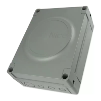
TheMC424controlunithasbeendesignedtocontrolWingo24Velectrome-
chanical actuators, for automated swing gates or doors. IMPORTANT! – Any
uses other than those specied herein or in environmental conditions
other than as stated in this manual are to be considered improper and
are strictly prohibited!
TheMC424controlunitoperatesonthebasisofacurrentsensitivitysystem
whichcheckstheloadofthemotorsconnectedtoit.Thesystemautomatically
detects travel stops, memorises the running time of each motor and recognises
obstaclesduringnormalmovement.Thisfeaturemakesinstallationeasieras
there is no need to adjust the working times nor the leaf delay.
Thecontrolunitispre-programmedforthenormalfunctions,whilemorespe-
cicfunctionscanbechosenfollowingasimpleprocedure(seechapter5).
ThecontrolunitisdesignedtobepoweredbyPS124bufferbatteriesasemer-
gency power supply in the event of a mains power failure (for further information
seechapter6.2).Itisalsodesignedtobeconnectedtothe“Solemyo”solar
energysystem(forfurtherinformationseechapter6.3).
PRODUCT DESCRIPTION
1
In order to explain certain terms and aspects of an automatic 2-leaf swing door
or gate system refer to the typical system shown in g 1.
Key to g. 1:
1.Wingo24Velectromechanicalactuator
2. Electromechanical actuator
3.Lucy24ashinglight
4. Key-operated selector switch
5.“PHOTO”pairofphotocells
6.“FOTO1”pairofphotocells
7.“PHOTO2”pairofphotocells
8. Control unit
In particular, please note that:
• Refer to the product instructions for the characteristics and connection of the
photocells.
•Activationofthe“PHOTO”pairofphotocellshavenoeffectonthegatedur-
ing opening, while they reverse movement during closing.
INSTALLATION
2
Summary
GENERAL SAFETY WARNINGS AND PRECAUTIONS .......... 1
1 – PRODUCT DESCRIPTION ................................. 1
2 – INSTALLATION .......................................... 1
2.1 - PRELIMINARY CHECKS FOR INSTALLATION ............ 2
2.2 - PRODUCT APPLICATION LIMITS ...................... 2
2.3 - INSTALLATION ..................................... 2
2.4 - ELECTRICAL CONNECTIONS ......................... 2
2.4.1 - Notes on connections .......................... 3
2.4.2 - Type of ALT input ............................. 3
2.4.3 - Examples of photocell connections: with the
“Everything in stand by” function active and the
Phototest function disabled ..................... 3
2.4.4 - Examples of photocell connections: with the Phototest
function active and the “Everything in stand by”
function disabled .............................. 3
2.5 - INITIAL START-UP AND ELECTRICAL CONNECTIONS .... 3
2.6 - AUTOMATIC LIMIT SWITCH SEARCH .................. 3
3 – TESTING AND COMMISSIONING ........................... 4
3.1 - TESTING .......................................... 4
3.2 - COMMISSIONING ................................... 4
4 – DIAGNOSTICS .......................................... 4
5 – PROGRAMMING ........................................ 4
5.1 - PRESET FUNCTIONS ................................ 4
5.2 - PROGRAMMABLE FUNCTIONS ....................... 4
5.2.1 - Direct programming ........................... 4
5.2.2 - First level programming: rst part ................ 4
5.2.3 - First level programming: second part ............. 5
5.2.4 - Second level functions ......................... 5
5.3 - PROGRAMMING MODES .............................5
5.3.1 - First level programming: functions ............... 6
5.3.2 - Second level programming: parameters ........... 6
5.3.3 - Deletion of memory ............................ 7
5.3.4 - Example of rst level programming .............. 7
5.3.5 - Example of second level programming ............ 7
5.3.6 - Programming diagrame ........................ 8
6 – FURTHER DETAILS: accessories ........................... 9
6.1 - CONNECTING A RADIO RECEIVER .................... 9
6.2 - CONNECTING MODEL PS124 BUFFER BATTERY ........ 9
6.3 - CONNECTING THE SOLEMYO SYSTEM ................ 9
7 – TROUBLESHOOTING (troubleshooting guide) ................ 9
8 – PRODUCT MAINTENANCE ................................ 9
DISPOSAL OF THE PRODUCT ............................. 9
TECHNICAL CHARACTERISTICS OF THE PRODUCT ......... 10
EC DECLARATION OF CONFORMITY ...................... 10
RADIO RECEIVER: SMXI - SMXIS ......................... 11
1 - PRODUCT DESCRIPTION ............................. 11
2 - AERIAL INSTALLATION ............................... 11
3 - MEMORISING A REMOTE CONTROL ................... 11
4 - DELETING ALL TRANSMITTERS ....................... 12
TECHNICAL CHARACTERISTICS OF THE PRODUCT ......... 12
IMAGES ............................................. I-V
Original instructions
EN

 Loading...