2.5 - Initial start-up and electrical connections
IMPORTANT! – Connections must be made exclusively by qualied per-
sonnel.
Afterpoweringupthecontrolunit,checkthatalltheLEDsashrapidlyforafew
seconds, then perform the following checks:
1.Checkthatthereisavoltageofapproximately30Vdconterminals9-10.If
not, unplug the unit immediately and carefully check the connections and
input voltage.
2.Afterinitiallyashingrapidly,theP1LEDwillindicatethecontrolunitiswork-
ingcorrectlybyashingregularlyat1secondintervals.Whenthereisavari-
ationintheinputs,the“P1”ledwillrapidlyashtwicetoshowthattheinput
has been recognised.
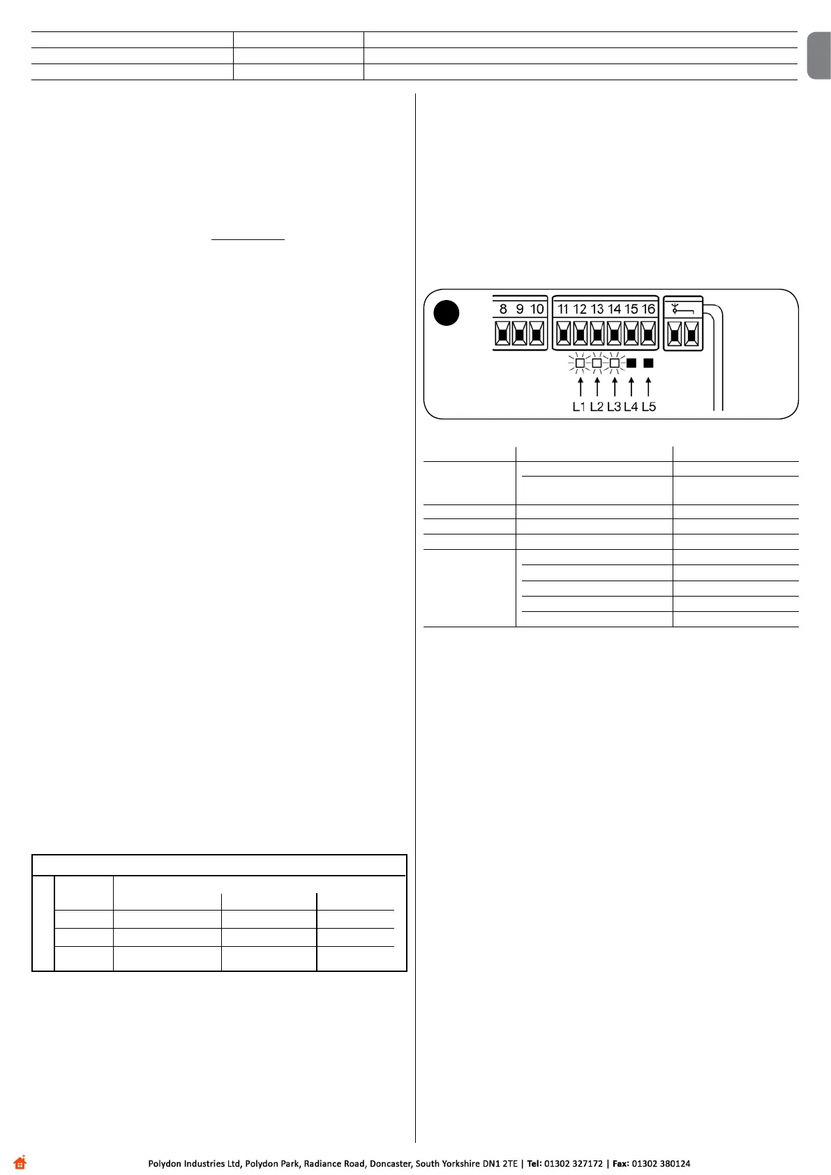
3. If the connections are correct, the LED for the “NC”-type inputs will be on,
whilethoseforthe“NO”typeinputsmustbeoff.Seeg. A and Table 2.
TABLE 2
INPUT INPUT TYPE STATUS LED
STOP STOPNC L1On
CONSTANTRESISTANCE L1On
STOP8.2KΩ
PHOTO NC L2On
FOTO1 NC L3On
STEP-BY-STEP NO L4Off
AUX OPENPARTIALLYtype1-NO L5Off
OPENPARTIALLYtype2-NO L5Off
OPENONLY-NO L5Off
CLOSEONLY-NO L5Off
FOTO2-NC L5On
4. Check that the relative LEDs switch on and off when the devices connected
to the inputs are operated.
5. Check that by pressing P2 both motors perform a short opening manoeuvre,
andthemotoroftheupperleafstartsrst.Blockthemanoeuvrebypress-
ing P2 again. If the motors do not start up for opening, invert the polarities
ofthemotorcables.If,however,therstonetomoveisnottheupperleaf,
operate jumper E (g. 2).
2.6 - Automatic search system for the limit switches
Onthesuccessfulcompletionofthevariouscontrols,starttheautomaticsearch
systemphaseforthelimitswitches.ThisworkisnecessaryastheMC424con-
trol unit must “measure” how long the opening and closing manoeuvres take
Thisprocedureiscompletelyautomaticanddetectsthemechanicalopening
and closing stops by measuring the load on the motors.
Warning! – If this procedure has already been carried out, in order to
reactivate it, the user must rst delete the memory (see the “Memory
de letion” chapter). In order to check whether the memory contains any
li mit switch parameters, turn the power supply to the control unit on
and then off again. If all the LEDs ash rapidly for approximately 6 sec-
onds, the me mory is empty. If, however, they only ash for 3 seconds,
the memory already contains some limit switch parameters.
Before starting limit switch searching, make sure that all the safety devices
areenabled(STOP,PHOTOandPHOTO1).Theprocedurewillbeimmediately
interrupted if a safety device triggers or a command arrives. The leafs MUST
be positioned at approximately mid-travel.
Procedure – Press the P2 button (g. 2) to start begin searching which
includes:
- Bothmotorsopenbriey.
- Motor closes the lower leaf until it reaches the mechanical closing stop.
- Theupperleafmotorclosesuntilitreachesthemechanicalclosingstop.
- Themotoroftheupperleafbeginstoopen.
- After the programmed delay, opening of the lower leaf begins. If the delay
isinsufcient,blockthesearchbypressingP1(g. 2),thenmodifythetime
(seechapter5).
- Thecontrolunitmeasuresthemovementrequiredforthemotorstoreachthe
opening mechanical stops.
- Completeclosingmanoeuvre.Themotorscanstartatdifferenttimes,theaim
is to prevent the leafs from shearing by maintaining a suitable delay.
English – 3
2.4.1 - Notes about connections
Most connections are extremely simple and many of them are direct connec-
tionstoasingleuserpointorcontact.Thefollowingguresshowexamplesof
how to connect external devices:
• Everything in stand by / Phototest connection
The“Everythinginstandby”functionisactiveasstandard.Itisexcludedauto-
matically only when the Phototest function is activated. Note - The “Everything
in stand by” and Phototest functions are alternatives as one excludes the other.
The“Everythinginstandby”functionallowsconsumptionstobereduced.Three
types of connections can be obtained:
- with “Everything in stand by” active (energy saving);seeelectricaldiagramin
g. 5a
-standardconnection:without“Everythinginstandby”andwithout“Phototest”;
see electrical diagram in g. 5b
-without“Everythinginstandby”andwith“Phototest”;seeelectricaldiagramin
g. 5c
Whenthe“Everythinginstandby”functionisactive,1minuteaftertheendof
a manoeuvre the control unit goes into “Everything in stand by”, turning off the
InputsandOutputstoreduceconsumptions.Thestatusisindicatedbythe“OK”
LEDwhichbeginstoashmoreslowly.WARNING – If the control unit is powered
fromaphotovoltaicpanel(“Solemyo”system)orabufferbattery,the“Everythingin
stand by” function must be activated as shown in the electrical diagram in g. 5a.
Whenthe“Everythinginstandby”functionisnotrequired,the“Phototest”func-
tionmaybeactivated.Thisveriesatthebeginningofamanoeuvrethatthe
connectedphotocellsoperatecorrectly.Tousethisfunction,rstconnectthe
photocells appropriately (see electrical diagram in g. 5c)andthenactivatethe
function. Note – When the phototest is activated, the inputs subjected to the
test procedure are PHOTO, PHOTO1 and PHOTO2. If one of these inputs is not
used it must be connected to terminal no. 8.
• Key switch connection
Example 1 (g. 7a): HowtoconnecttheswitchinordertoperformtheSTEP-
BY-STEPandSTOPfunctions
Example 2 (g.7b): HowtoconnecttheswitchinordertoperformtheSTEP-
BY-STEPandoneoftheauxiliaryinputfunctions(PARTIALOPENING,OPEN
ONLY,CLOSEONLY…)
Note – For electrical connections with the “Everything in stand by” function
active, see “Everything in stand by/Phototest function” in this paragraph 2.4.1.
• Connection for Gate Open Indicator / Electric lock (g. 8)
If the gate open indicator has been programmed, the output can be used as an
opengateindicatorlight.Thelight,ashesslowlyduringopeningandquickly
duringclosing;Ifitisonbutdoesnotash,thisindicatesthatthegateisopen.
If the light is off, the gate is closed. Se the output has been programmed as an
electric lock, it is activated for 3 seconds each time opening begins.
2.4.2 - STOP type input
TheMC424controlunitcanbeprogrammedfortwotypesofSTOPinput:
- NC type STOP for connecting up to NC type contacts.
- Constant resistance STOP. It enables the user to connect up to the con-
trolunitofdeviceswith8.2kΩconstantresistance(e.g.sensitiveedges).
Theinputmeasuresthevalueoftheresistanceanddisablesthemanoeuvre
when the resistance is outside the nominal value. Devices with normally open
“NO”ornormallyclosed“NC”contacts,ormultipledevices,evenofdifferent
types,canbeconnectedtotheconstantresistanceSTOPinput,provided
thatappropriateadjustmentsaremade;seeTable1.
WARNING! – If the constant resistance STOP input is used to connect
devices with safety functions, only the devices with 8.2 KΩ constant
will resistance output guarantee the fail-safe category 3.
Notes to Table 1:
Note 1 – Any number of NO devices can be connected to each other in paral-
lel, with an 8.2 KΩ termination resistance (g. 9a). For electrical connections
with the “Everything in stand by” function active, see “Everything in stand by/
Phototest function” in this paragraph 2.4.1.
Note 2 – The NO and NC combination can be obtained by placing the two con-
tacts in parallel, and placing an 8.2 KΩ resistance in series with the NC contact. It
is, therefore, possible to combine 3 devices: NO, NC and 8.2 KΩ (g. 9b).
Note 3 – Any number of NC devices can be connected in series to each other
and to an 8.2 KΩ resistance (g. 9c).
Note 4 – Only one device with an 8.2 KΩ constant resistance output can be
connected; multiple devices must be connected “in cascade” with a single 8.2
KΩ termination resistance (g. 9d).
A
1stdevicetype:
NO NC 8,2 KΩ
In parallel (note 1) (note 2) Inparallel
NC (note 2) Inseries(note 3) Inseries
8,2 KΩ In parallel In series (note 4)
TABLE 1
second device type:
CLOSE NO Onlycarriesouttheclosingmanoeuvre
PHOTO2 NC PHOTO2function
DISABLED — No function
EN

 Loading...


