ENGLISH – 15
ELECTRICAL CONNECTIONS
4
4 ELECTRICAL CONNECTIONS
4.1 PRELIMINARY CHECKS
f
All electrical connections must be made with the sys-
tem disconnected from the mains electricity and with the
emergency power supply (if present in the automation)
disconnected.
a
The connection operations must only be carried out by
qualied personnel.
To make the electrical connections:
1. Open the locking hook (A) using the key provided
2. Remove the screws (B)
3. Remove the cover (C) (“Figure 30")
A
B
C
30
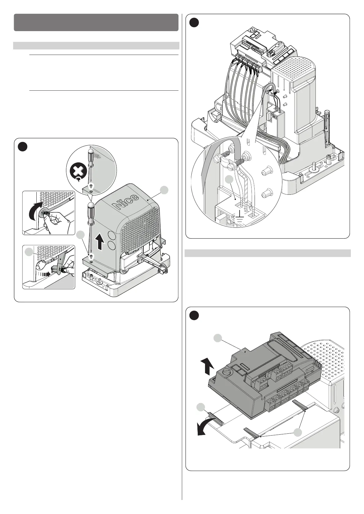
4. Feed the power cable through the relevant hole (leave 20/30 cm of
free cable) and connect it to the relevant terminal clamp (D)
5. Lock the cable around the sheath using the cable clamp provided
6. Insert all the connecting cables into the various devices, leaving
them 20–30 cm longer than necessary. Refer to “Table 4” for the
type of cables and to “Figure 33” for the connections
7. Use a cable tie to group all the cables entering the gearmotor (“Fig
-
ure 31")
D
31
4.2 REMOVING THE CONTROL UNIT
The control unit can be removed whenever there is difculty in making the
electrical connections.
1. Hold the control unit (A) tightly with one hand
2. Remove any cables or terminals
3. Carefully press the plastic support (B) downwards and remove the
control unit
4. The control unit is bound to the two supports (C) (“Figure 32")
A
B
C
32