ENGLISH – 23
5.4 CHECKING THE AUTOMATION’S MOVEMENT
Once the leaf length has been learned, it is advisable to carry out a few
manoeuvres in order to verify that the automation moves properly
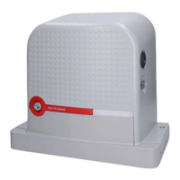
IBT4N
L1
L2
L3
L4
L5
L6
L7
L8
R
44
– Press the
f
button to command an “Open” manoeuvre; check
that the automation opens regularly without any variations in speed; the
leaf must only slow down when it is between 70 cm and 50 cm from the
opening limit switch and then stop at 2–3 cm from the opening mechan
-
ical stop when the limit switch triggers
– Press the
h
button to command a “Close” manoeuvre; check
that the automation closes regularly without any variations in speed; the
leaf must only slow down when it is between 70 cm and 50 cm from the
closing limit switch and then stop at 2–3 cm from the closing mechani
-
cal stop when the limit switch triggers
– During the manoeuvre, check that the warning light ashes at intervals
of 0.5 seconds on and 0.5 seconds off. If present, also check the ash
-
es of the light connected to the OGI terminal: slow ashing during open-
ing, quick ashing during closing
– Open and close the gate several times to make sure that there are no
points of excessive friction and that there are no defects in the assembly
or adjustments
– Check that the ROBUS gearmotor, rack and limit switch brackets are
stably and safely secured, and are suitably resistant also during sudden
acceleration or slowdown movements of the automation
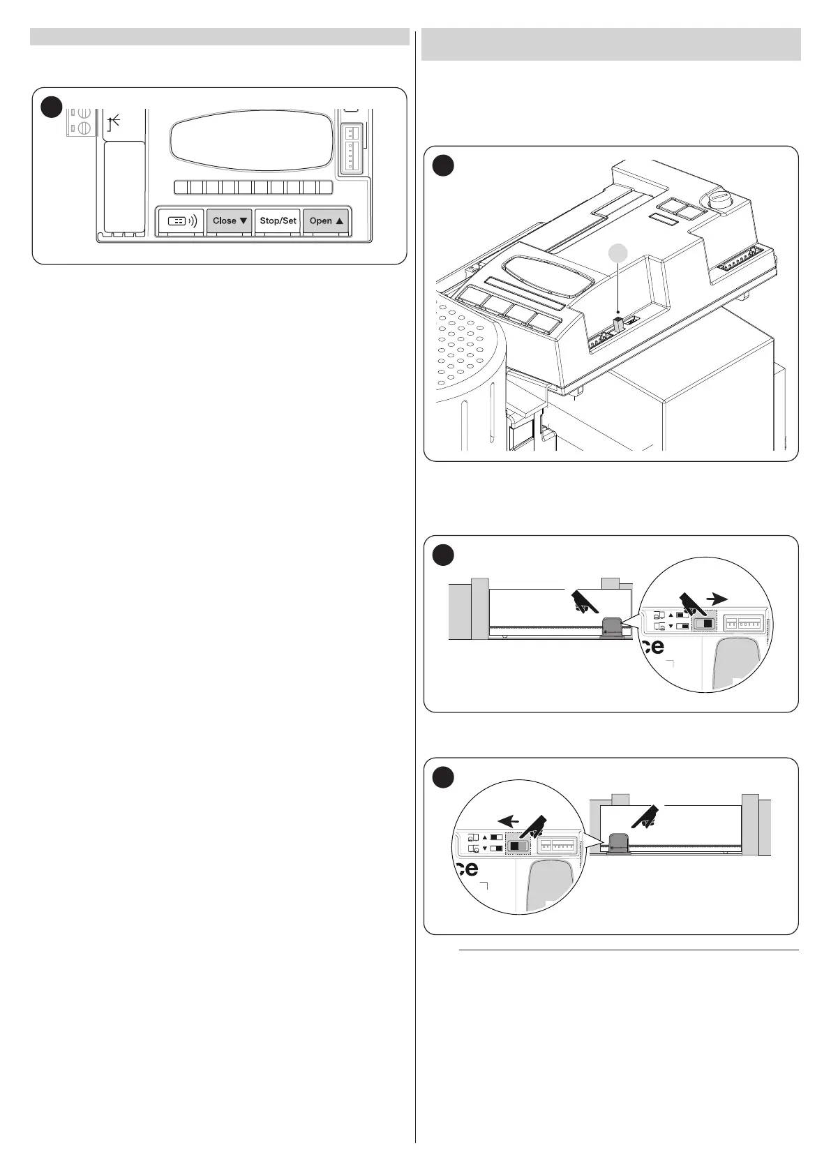
5.5 INVERTING THE DIRECTION OF MOTOR
ROTATION
To modify the rotation direction, simply position selector (A) in the desired
direction and start the BlueBus search procedure (refer to the “Device
learning” chapter on page 21).
It is also necessary to repeat the position acquisition procedure (refer to
the “Leaf length learning” chapter on page 21).
45
With the selector positioned as shown in Figure 46 (default setting, typ
-
ical installation), the automation is opened by moving it in the direction
of the motor.
46
With the selector positioned as shown in Figure 47, the automation is
opened by moving it in the direction opposite to that of the motor.
47
m
The change of direction will not be considered until the
start of the device acquisition procedure (refer to the “
Device learning” chapter on page 21 and the “Leaf length
learning” chapter on page 21).