ENGLISH – 21
5.2 DEVICE LEARNING
After connecting the power supply, the control unit must learn the devices
connected to the “BlueBus” and “STOP” inputs, and also the rotation
direction of the motor set on the selector. Moreover, this procedure rec
-
ognises and memorises the input and output expansion board connected
to the control unit. Before this phase, LEDs “L1” and “L2” will ash to
indicate that recognition of the devices must be carried out.
m
The learning phase must be carried out even if no device
is connected to the control unit.
To do this:
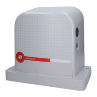
1. simultaneously press and hold the
f
and
g
but-
tons
2. release the buttons when LEDs “L1” and “L2” start ashing quickly
(after roughly 3 seconds)
3. wait a few seconds until the control unit has completed the device
learning phase
4. once this phase terminates, the “Stop” LED must be lit and LEDs
“L1” and “L2” must switch off. In case of initial installation, LEDs
“L3” and “L4” will start ashing.
12V OSE
Bluebus
Aerial
39
The self-learning phase of the connected devices can be repeated at any
time also after the installation, for example whenever a device must be
added or removed.
m
If the motor’s rotation direction must be reversed, the de-
vice learning procedure must be performed again.
5.3 LEAF LENGTH LEARNING
5.3.1 PRELIMINARY CHECKS
Once the devices have been learned, LEDs “L3” and “L4”; will start ash-
ing; this means that the control unit must recognise the length of the gate
leaf (distance between the closing and opening limit switches); this meas
-
urement is necessary to calculate the slowdown points and the partial
opening point.
Before proceeding, make sure that the automation is unlocked. If not, un
-
lock the motor and close the automation manually (see “Manually un-
locking and locking the gearmotor” paragraph)
With the automation closed, three situations may occur:
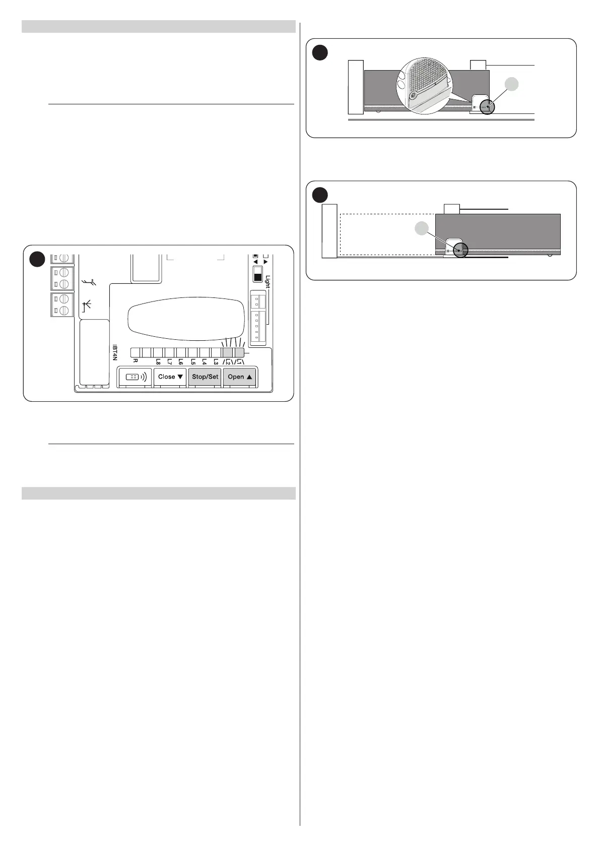
– the status LED (L) is lit steady red (correct situation). The motor has
correctly detected the closing limit switch
– the status LED (L) is lit steady green (position selector of the motor to be
inverted). Verify the correct position (“Figures 26 and 27”).
– the status LED (L) is off. Verify the correct position of the limit switch
(“Figures 19 and 20”).
The status LED (L) is lit steady red
L
40
With the motor unlocked, position the gate in the opening position. In this
case the status LED (L) must light up green. Close the gate and lock the
motor again.
L
41
The status LED (L) is lit steady green
Verify the correct position of the motor position selector by observing that
indicated in the paragraph Installing the gearmotor (“Figures 26 and
27”).