12 – ENGLISH
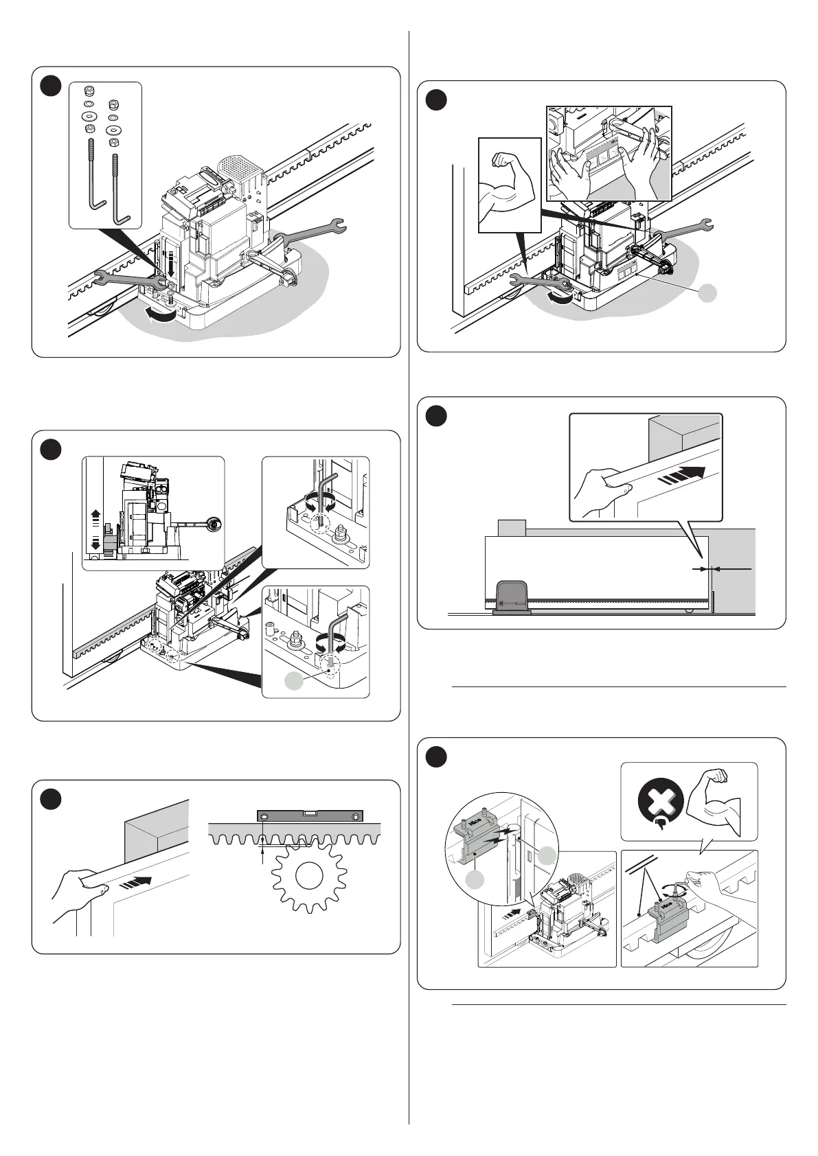
8. insert the washers and nuts provided and tighten them slightly
(“Figure 15")
15
9. adjust the gearmotor’s height using the adjuster grub screws (H)
and move the pinion to roughly 1 or 2 mm from the rack, so as to
prevent the leaf’s weight from bearing on the gearmotor (“Figure
16")
H
16
10. manually open and close the gate leaf and check that it slides
smoothly. Moreover, check that the rack is always aligned with re
-
spect to the pinion (“Figure 17")
2 mm
17
11. vigorously tighten the nuts to secure the gearmotor to the founda-
tion plate and apply the sticker (I) relative to the unlocking instruc-
tions (“Figure 18")
Per Sblocca
r
e - Pour débrayer - T
o unblock
Um zu entriegeln - Para desbloquear
Odblokowanie - Om te deblokke
ren - Отпереть
2 3
1
Per Sbloccare - Pour débrayer - To unblock
Um zu entriegeln - Para desbloquear
Odblokowanie - Om te deblokkeren - Отпереть
2 3
1
I
18
12. slide the gate leaf open by hand, stopping it 2/3 before the me-
chanical stop (“Figure 19")
2-3 cm
19
13. apply the limit switch bracket (L) to the rack as close as possible
to the sensor (M) and fasten it with the appropriate grub screws
(“Figure 20")
a
Do not apply excessive pressure while fastening the limit
switch bracket.
L
M
20
a
The limit switch bracket with its magnet must not be
aligned with the sensor. In this case, its load capacity is
poor and the gate risks not stopping correctly.