20 – ENGLISH
a
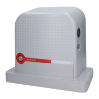
In Slave mode with products of the previous generation
(RBA3), the Bluebus connecting cables between the two
motors must be inverted.
Bluebus
MASTER
Bluebus
SLAVE
Bluebus
Bluebus
2 21 1
37
a
When connecting 2 ROBUS in the Master-Slave mode,
make sure that:
– All devices are connected to the Master ROBUS, including the
radio receiver
– When using back-up batteries, each motor has its own battery
– All programming activities performed on the Slave ROBUS are
ignored (those on Master ROBUS override the others) except
for those mentioned in “Table 7”.
Table 7
PROGRAMMING ACTIVITIES ON THE SLAVE ROBUS INDEPENDENT FROM
THE MASTER ROBUS
Level 1 functions (ON-OFF
functions)
Level 2 functions (adjustable parameters)
Stand-by Motor speed
Peak OGI output
Slave mode Motor force
Error list
On Slave it is possible to connect:
• a ashing light (Flash)
• an own Open Gate Indicator (OGI)
• a sensitive edge (Stop)
• an own command device (SbS) that controls the opening of the
Slave leaf only
The Photo input is not used on the Slave. The automatic closing,
close after photo, always close and pre-ashing parameters are
deactivated. Moreover, the internal radio is inhibited.
FINAL CHECKS AND START-UP
5
5 FINAL CHECKS AND START-UP
5.1 POWER SUPPLY CONNECTION
a
The power supply connections must only be made by
qualied and experienced personnel possessing the nec-
essary requirements and in full conformity to the laws,
regulations and standards in force.
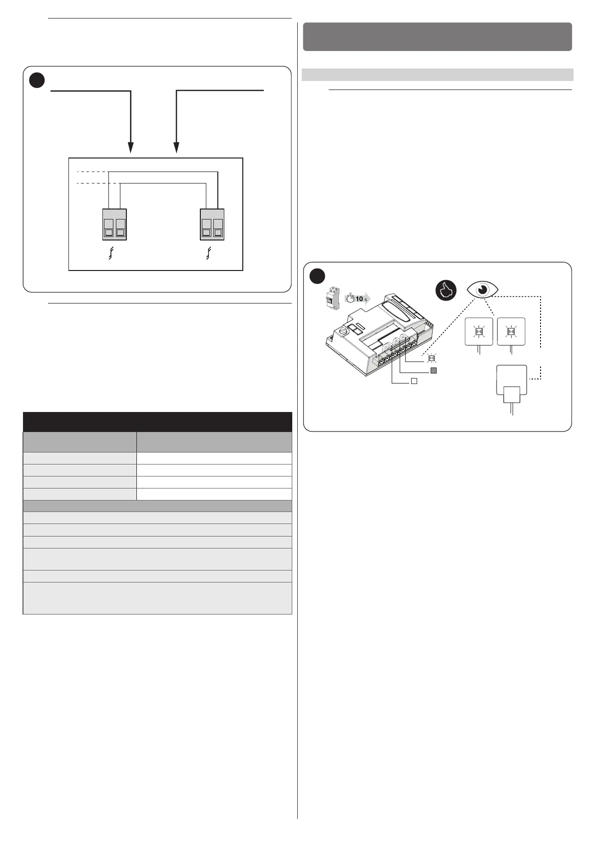
As soon as the product is powered, a few simple checks should be carried
out:
1. check that the BlueBus LED ashes regularly with one ash per
second.
2. make sure that the LEDs on the photocells (both the TX and RX)
also ash; the type of ashing is irrelevant, since it depends on
other factors.
3. check that the warning light and the status light connected to the
FLASH output are off.
4. check that the NC Photo LED is lit.
5. check that the courtesy light is off. (Where available)
ON
OFF
TX RX
FLASH
BlueBus
stop NO-NC-8k2
Photo NC
38
If the above conditions are not satised, immediately switch off the power
supply to the control unit and carefully check the electrical connections.
Further useful information on fault search and diagnosis is included in the
“Troubleshooting” paragraph (page 38).