40 – ENGLISH
9.3 SIGNALLING THROUGH WARNING LIGHT
During the manoeuvre, the “FLASH” warning light ashes once every second; whenever anomalies occur, shorter ashes are emitted; the ashes are
repeated twice with a one-second pause in between.
Table 24
FLASH WARNING LIGHT SIGNALS
Fast ashes Cause ACTION
2 ashes
1-second pause
2 ashes
Intervention of a photocell
At the start of the manoeuvre, one or more photocells are blocking the movement; check whether
there are any obstacles. During the manoeuvre, this is normal if an obstacle is present.
3 ashes
1-second pause
3 ashes
Intervention of the “Motor
Force” limiter
During its movement, the automation experienced excessive friction; identify the cause.
4 ashes
1-second pause
4 ashes
Triggering of the STOP
input
At the start of the manoeuvre or during the movement, the STOP input intervened; identify the
cause.
5 ashes
1-second pause
5 ashes
Internal parameter
memorisation error
Wait at least 30 seconds, then try giving a command. if the condition persists, it means there is a
malfunction and the electronic board has to be replaced.
6 ashes
1-second pause
6 ashes
The maximum number of
manoeuvres per hour limit
has been exceeded
Wait for a few minutes until the manoeuvre limiting device drops to under the maximum limit.
7 ashes
1-second pause
7 ashes
Error in the internal electric
circuits
Disconnect all the power circuits for a few seconds and then try giving a command again; if the
condition persists, it means there is a serious fault on the electronic board or on the motor cabling.
Perform any necessary checks and replacements.
8 ashes
1-second pause
8 ashes
Command already present
Another command is already present. Remove the command present to be able to send other
commands.
9 ashes
1-second pause
9 ashes
Automation stopped The automation was stopped by a “Stop automation” command
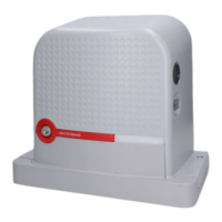
9.4 SIGNALS ON THE CONTROL UNIT
The control unit has a series of LEDs, each of which can emit special sig-
nals both during regular operation and when an anomaly occurs.
For further information, refer to “Table 27” and “Table 28”
A BlueBus LED
B Led Photo, Sbs, Stop
C “L1 ... L8” programming LEDs
D Led Radio "R"
24V
+ -
12V OSE
Bluebus
Aerial
GND
Stop
Flash
Photo
OGI
SbS
C
D
59
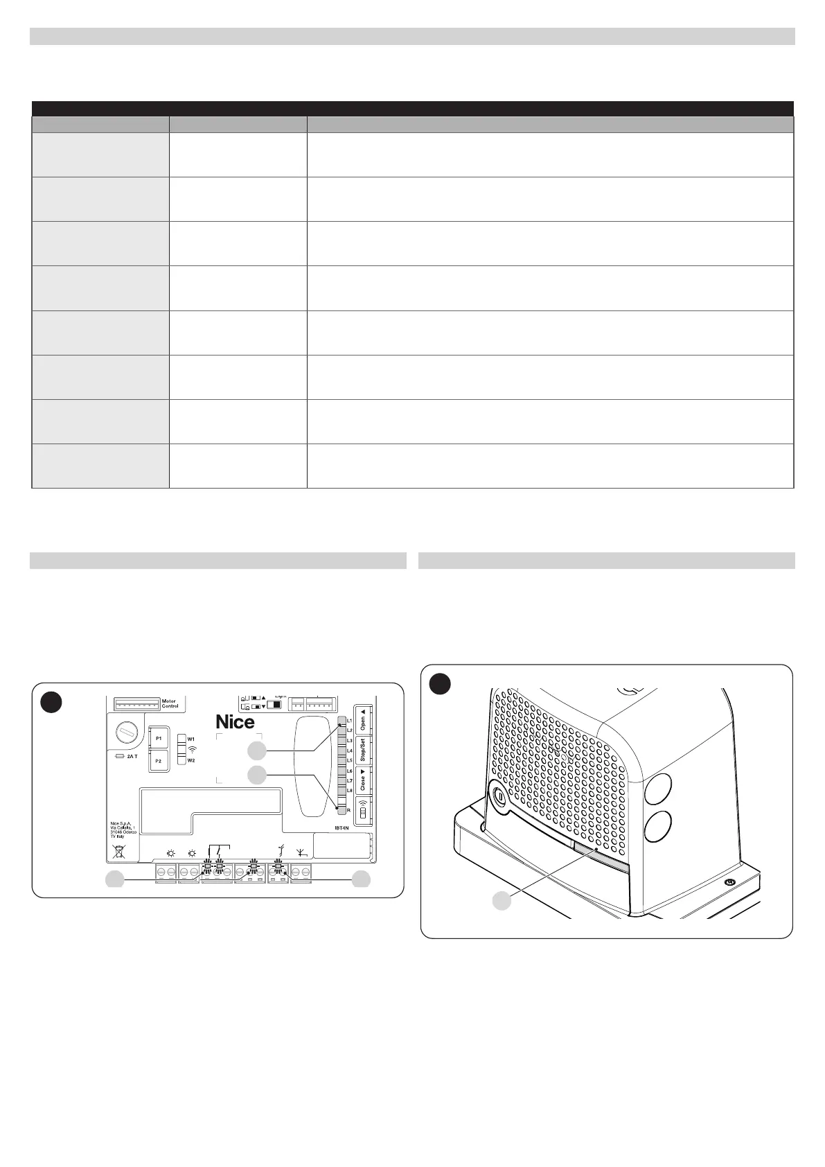
9.5 LUMINOUS SIGNALS
9.5.1 STATUS LIGHT
The motor status light (A) (“Figure 60”) is made up of 2 colours (red and
green) and has the function of signalling any anomalies. “Table 25” shows
the potential switch-on statuses.
A
60