25
External RF driver
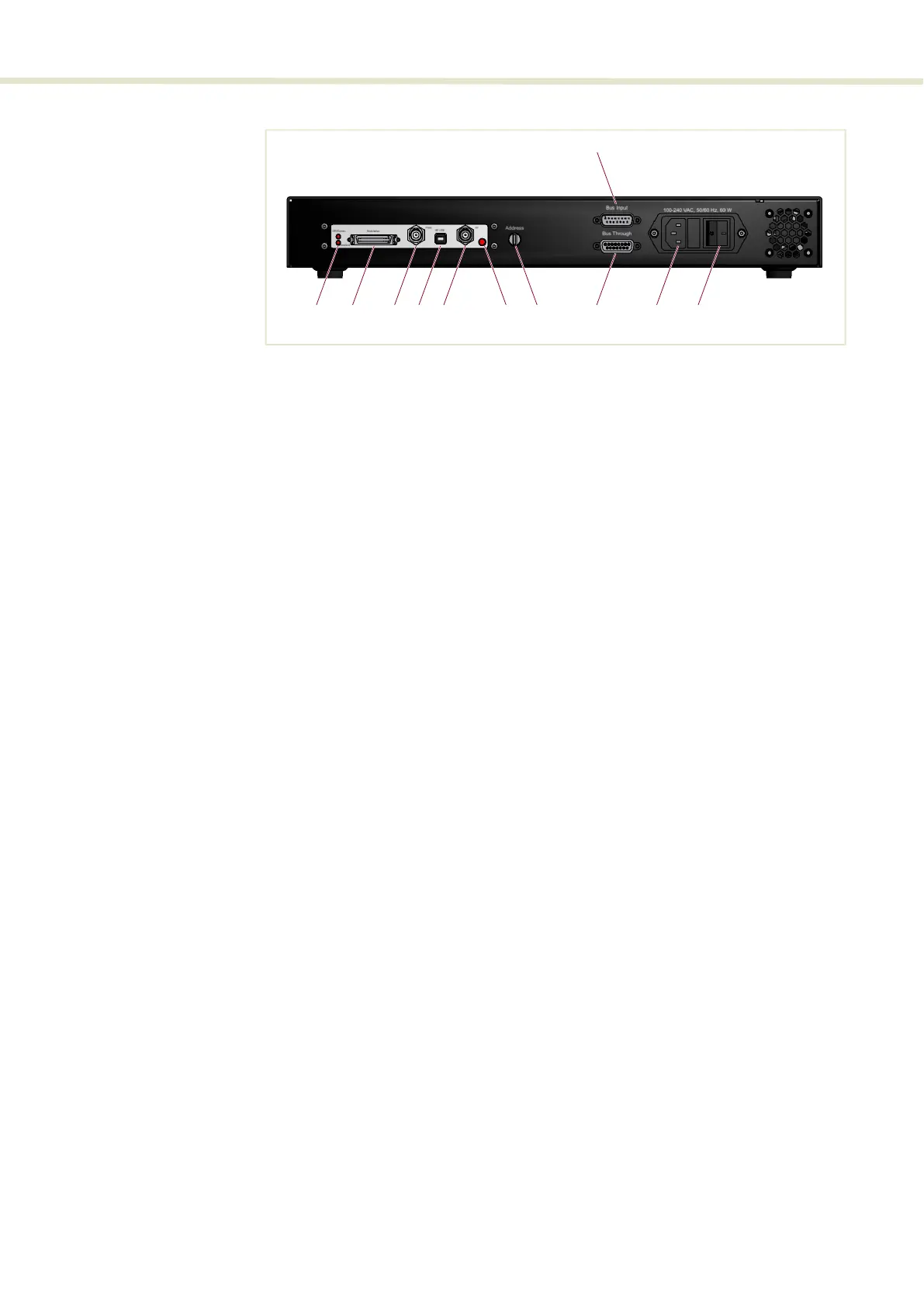
ERD - rear panel Figure 9 External RF Driver – rear panel
LEDs
• Power/comms LED – External bus communication and power connected
• Interlock LED– indicates if the Interlock circuit is open.
• RF LED – RF signal is transmitting
Modulation connector
If Fast Wavelength Switching (FWS) is required, an optional SuperK COMMAND
module is connected to this port. A COMMAND module can connect to external
signaling to drive FWS through the ERD and the SELECT. For more information
refer to Appendix D.
Reserved for future use
PWM and RF USB ports are reserved for future use at this time and so not for use
with the SELECT system.
RF out
BNC output port transmitting RF signal to one of two RF input ports on the
SELECT.
Address selector
When multiple modules are connected to the External bus daisy chain, this switch
must be set to a unique number for the module before turning on power.
Bus input & through port
DB-15 in and out ports for External bus daisy chain connectivity
AC mains input
Standard C14 input connector for a C13 power cord.
71 2 83 4 5 6 10
9
11
1 Power/comms and interlock LEDs 7 Address selector (external bus)
2 Modulation connector 8 Bus through port (external bus)
3 PWM – reserved for future use 9 Bus input (external bus)
4 RF USB – reserved for future use 10 AC mains input - C14 line connector
5 RF Out 11 AC mains ON/OFF switch
6 RF Out LED indicator