43
4 Using CONTROL
CONTROL overview
CONTROL includes multiple panels and a selection of menu drop down items in
the upper left corner. Figure 27 shows CONTROL’s main panels and menu; their
functions are described in the table below. This chapter only describes
CONTROL functions related to the SuperK SELECT, for all other functionality,
refer to the specific SuperK documentation.
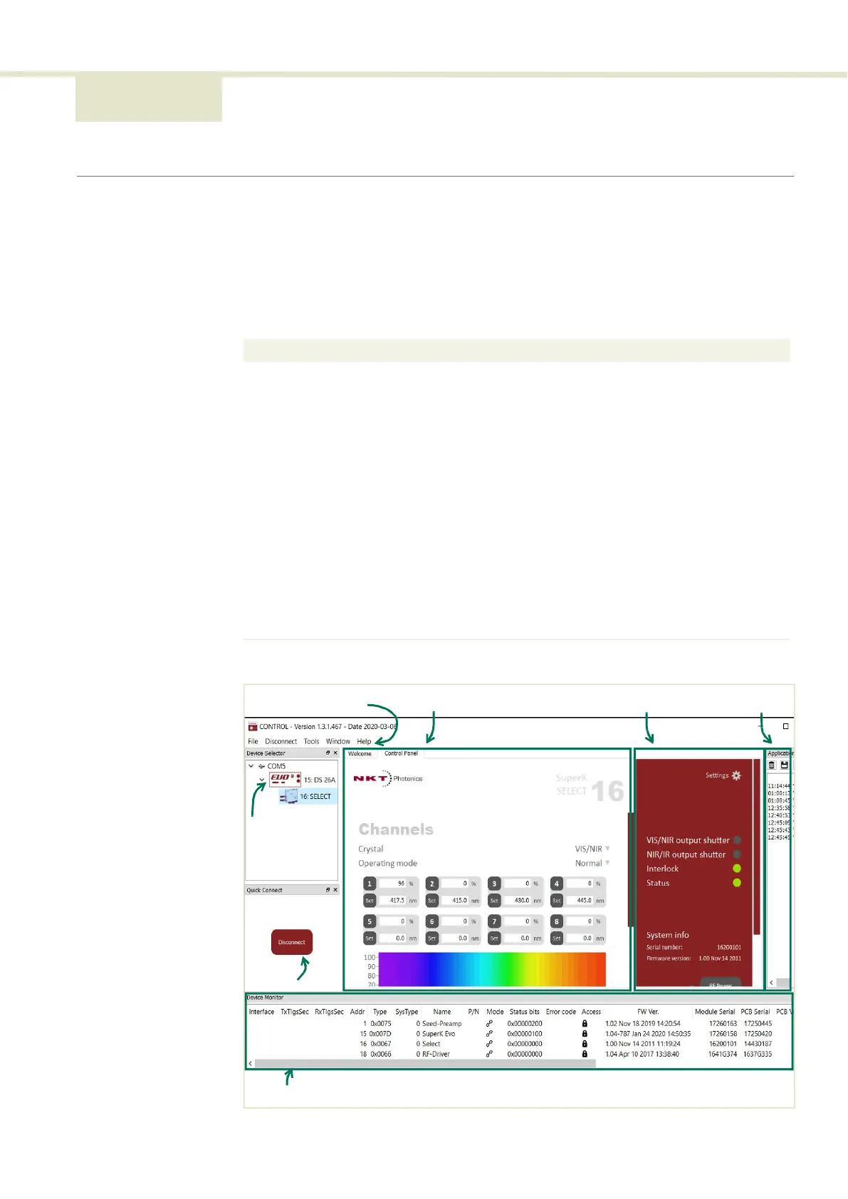
Figure 27 CONTROL panel navigation
Panel Function See
Device
Selector
Selectable list of connected devices (lasers and
accessories) sorted by the PC port they are
connected to.
Device Selector on
page 44
Quick
Connect
Provides a button when clicked, scans all available PC
ports for connected NKTP products.
Refer to SuperK laser
documentation.
Status Panel This panel displays the selected device status,
emission control and a CONTROL settings menu.
Status Panel on page 45
Menu Items Five drop down menus with multiple functions. Refer to SuperK laser
documentation.
Control Panel The control panel provides adjustable settings for the
selected device. For the SuperK SELECT, CONTROL
includes configuration for wavelength and power
level for up to 16 channels.
Control panel on page 49
Application
Log
This panel displays debug log output that can also be
saved to a file.
Refer to SuperK laser
documentation.
Device
Monitor
To help with troubleshooting, this panel displays
multiple port and device module parameters.
Refer to SuperK laser
documentation.
Menu Items Control Panel Status Panel Application Log
Device Monitor
Quick
Connect
Device
Selector
List