33
Electrical Connections
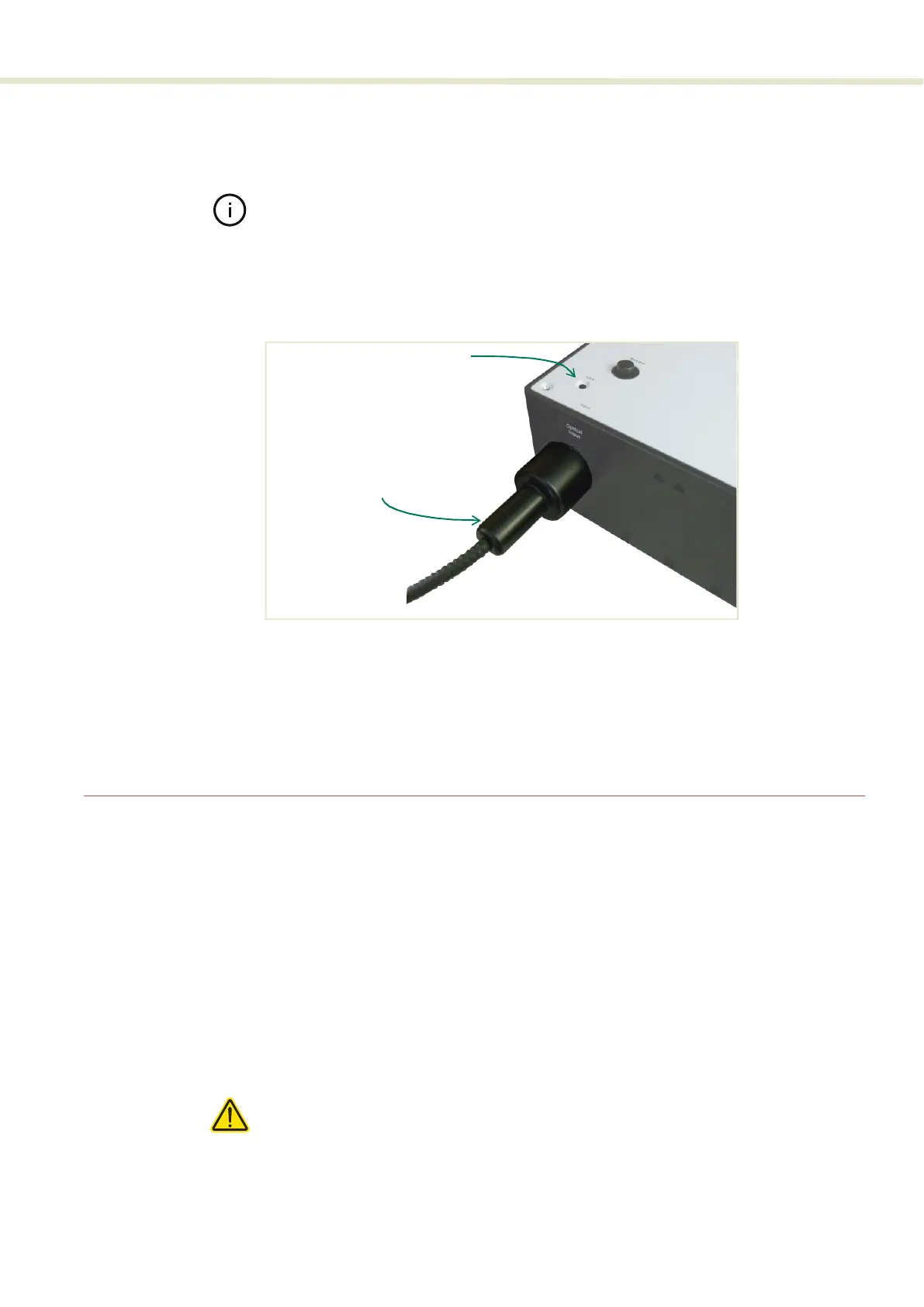
5. Push the collimator into the receptacle until its collar rests against the
chassis. As you push it in, the collimator will encounter some resistance, and
you may feel two distinct clicks as it locks in place.
Note: Again, when seating the collimator in the aperture, you may need to rotate
the collimator slightly to align the collimator key with the alignment slot.
6. To secure the collimator in the receptacle, tighten the lock screw shown in
Figure 15 using a 2.5 mm hex key (Allen key).
Figure 15 Collimator lock screw
Optical output All optical outputs are free space> NKT Photonics can provide SuperK CONNECT
accessories and collimators as described in the document:
SuperK CONNECT and Fiber Delivery Product Guide
Electrical Connections
Single ERD system For basic operation, connect the External bus from the SuperK laser to the
SELECT and to the External RF Driver (ERD) where the bus is looped back with
the included bus defeater. The RF coaxial BNC port of the ERD must be
connected to the RF1 BNC port of the SELECT. Finally, a 50 Ω RF
terminator
should be placed on the unused RF2 BNC port of the SELECT. Follow
Procedure 3 to make the connections.
Procedure 2 Electrical connections for a SELECT with a single ERD
1. Disconnect power from the laser.
Caution: If the laser is powered ON when connecting the external bus cable,
DAMAGE can occur to both the laser and the SELECT.
2. Using an External bus cable, connect the External bus connector of the
SuperK laser to the Bus Input connector (item D of Figure 16) of the SELECT.
Inserted
collimator
Lock screw
2.5 mm hex key