75
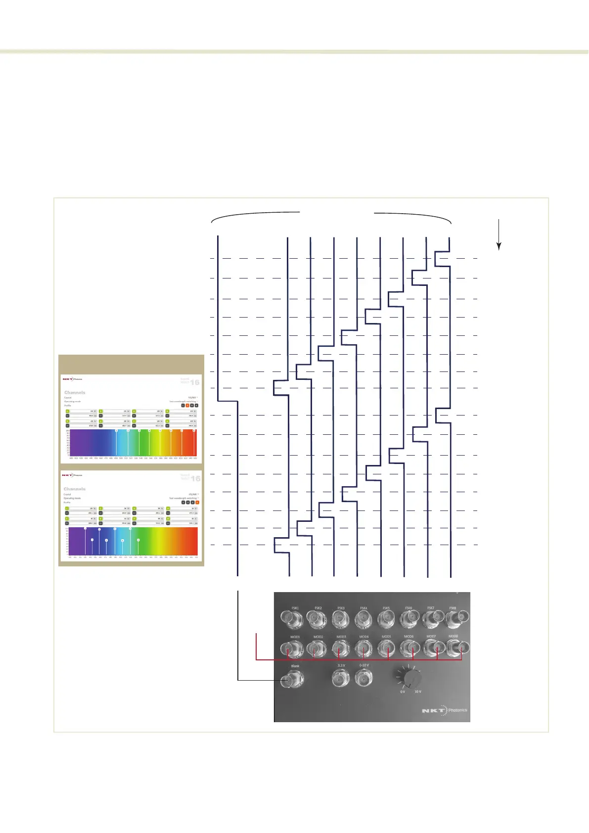
Signaling and CONTROL configuration
6. Using BNC cabling and splitters, connect the MOD1 to 8 pins to the +3.3 V
output pin on the COMMAND. When wavelengths are selected with FSK
inputs, the corresponding MOD pin must be pulled high.
7. Connect the FSK1 to 8 and BLANK pins to your application.
8. The system is ready and channels are selected based on the signals shown
in Figure 50.
Figure 50 Fast wavelength switching: 16 λ setup
CONTROL Channel/Prole
Prole 2
V+
MOD1in
ch1 prole 2
ch2 prole 2
ch3 prole 2
ch4 prole 2
ch5 prole 2
ch6 prole 2
ch7 prole 2
ch8 prole 2
FSK1in FSK2in FSK3in FSK4in FSK5in FSK6in FSK7in FSK8inBlankin
V+
V+
0V
ch1 prole 4
ch2 prole 4
ch3 prole 4
ch4 prole 4
ch5 prole 4
ch6 prole 4
ch7 prole 4
ch8 prole 4
V+
0V
V+
0V
V+
0V
V+
0V
V+
0V
V+
0V
V+
0V0V
Prole 4
AOTF Channel selected