35
Electrical Connections
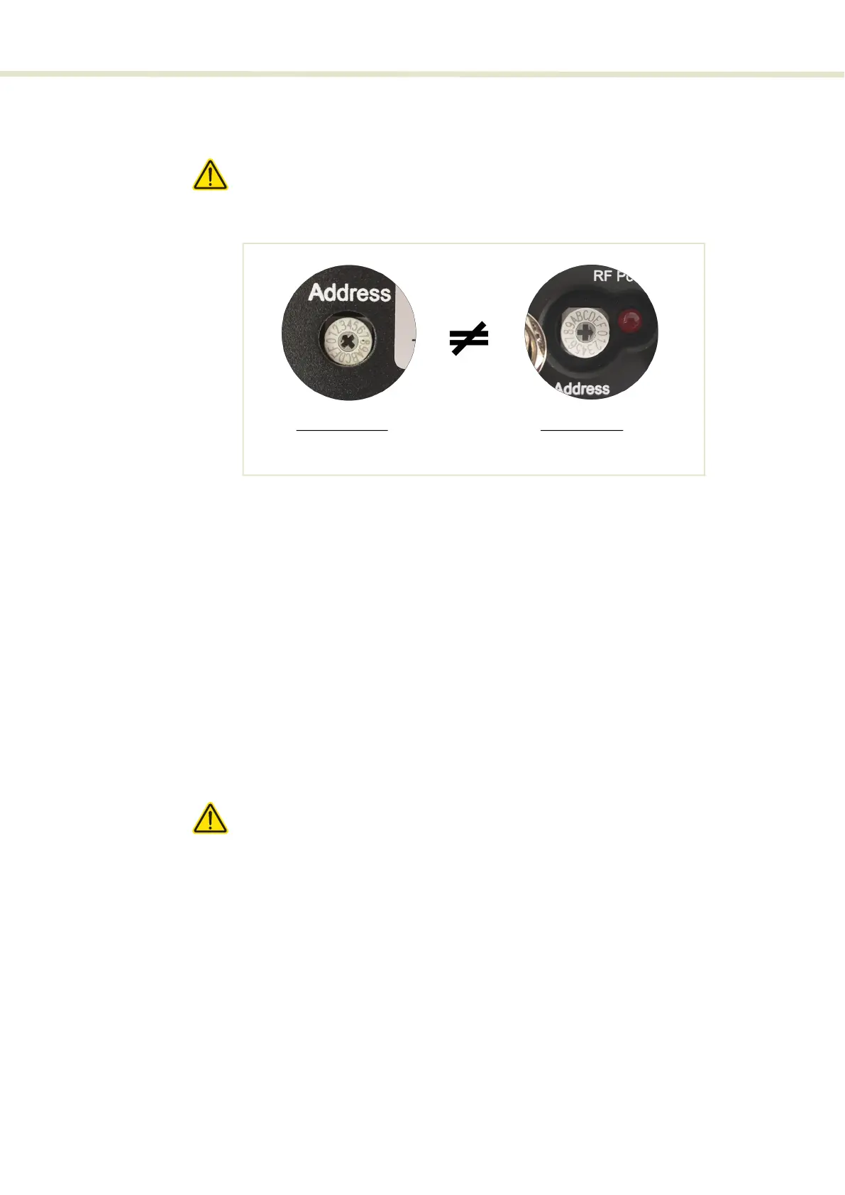
6. Set the address bus select switches to a unique address for the SELECT and
ERD as shown in Figure 19.
Caution: All modules on the External bus must use a unique address. A bus con-
flict and the system communication failure occurs when two or more modules are
set to the same address.
Figure 19 Setting External bus addresses - single ERD system
7. Connect AC mains power to the ERD.
8. Turn ON the laser and ERD. Check that the SELECT is available in the Device
Selector panel of CONTROL (see “Device Selector” on page 44)
Dual ERD system For basic operation, connect the External bus from the SuperK laser to the
SELECT and to both External RF Drivers (ERDs) where the bus is looped back
using the included bus defeater on the last module in the bus chain. The RF
coaxial BNC port of ERD 1 and ERD 2 must be connected to the RF1 and RF 2
BNC ports respectively on the SELECT. Follow Procedure 3 to make the
connections.
Procedure 3 Electrical connections for a SELECT with dual ERDs
1. Disconnect power from the laser.
Caution: If the laser is powered ON when connecting the external bus cable,
DAMAGE can occur to both the laser and the SELECT.
2. Using an External bus cable, connect the External bus connector of the
SuperK laser to the Bus Input connector (item D of Figure 20) of the SELECT.
External RF Driver:
Bus address = 2
SELECT module:
Bus address = 0