Signaling and CONTROL configuration
72
5. Set the power level desired in one of the profile channels. This sets the
power level to be identical for all configured channels in each profile.
6. Using a BNC cable, connect the MOD1 pin to the +3.3 V output pin on the
COMMAND. When wavelengths are switched with constant amplitude, the
MOD pin must be pulled high.
7. Connect the FSK1 and BLANK pins to your application.
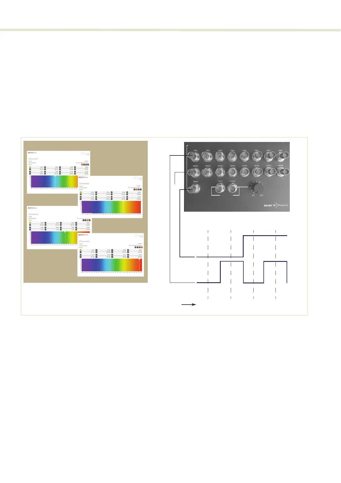
8. The system is ready and channels are selected based on the signals shown
in Figure 48.
Figure 48 Fast wavelength switching: 2 or 4 λ setup
Four 8-channel
profile switching
The system is also capable to switch the AOTF across all four 8-channel profiles
in Fast Wavelength Switching mode by connecting application signals to module
pins Blank and FSK1. Table 11 shows a truth table demonstrating the profiles
selected based on the input signals levels.
Figure 49 shows the configuration in CONTROL and how the profiles are
selected based on the input signals to the two pins. To set up four 8-channel
profile switching, follow the steps in Procedure 8.
Table 12 4 profile FWS truth table
Wavelengths 1 to 4 Selectionin
Blankin
Test
Outputs
V+
CONTROL Channel/Prole
ch1 - prole 3
ch1 - prole 4
AOTF channel selected
ch1
prole 1
ch1
prole 2
ch1
prole 3
ch1
prole 4
V+
0V
V+
0V
FSK1in
Blankin
MOD1in
Signals
ch1 - prole 1
ch1 - prole 2
FSK1 Blank Profile selected
Low Low Profile 1 Channels 1 to 8
High Low Profile 2 Channels 1 to 8
Low High Profile 3 Channels 1 to 8
High High Profile 4 Channels 1 to 8