Signaling and CONTROL configuration
76
Modulating
emission power
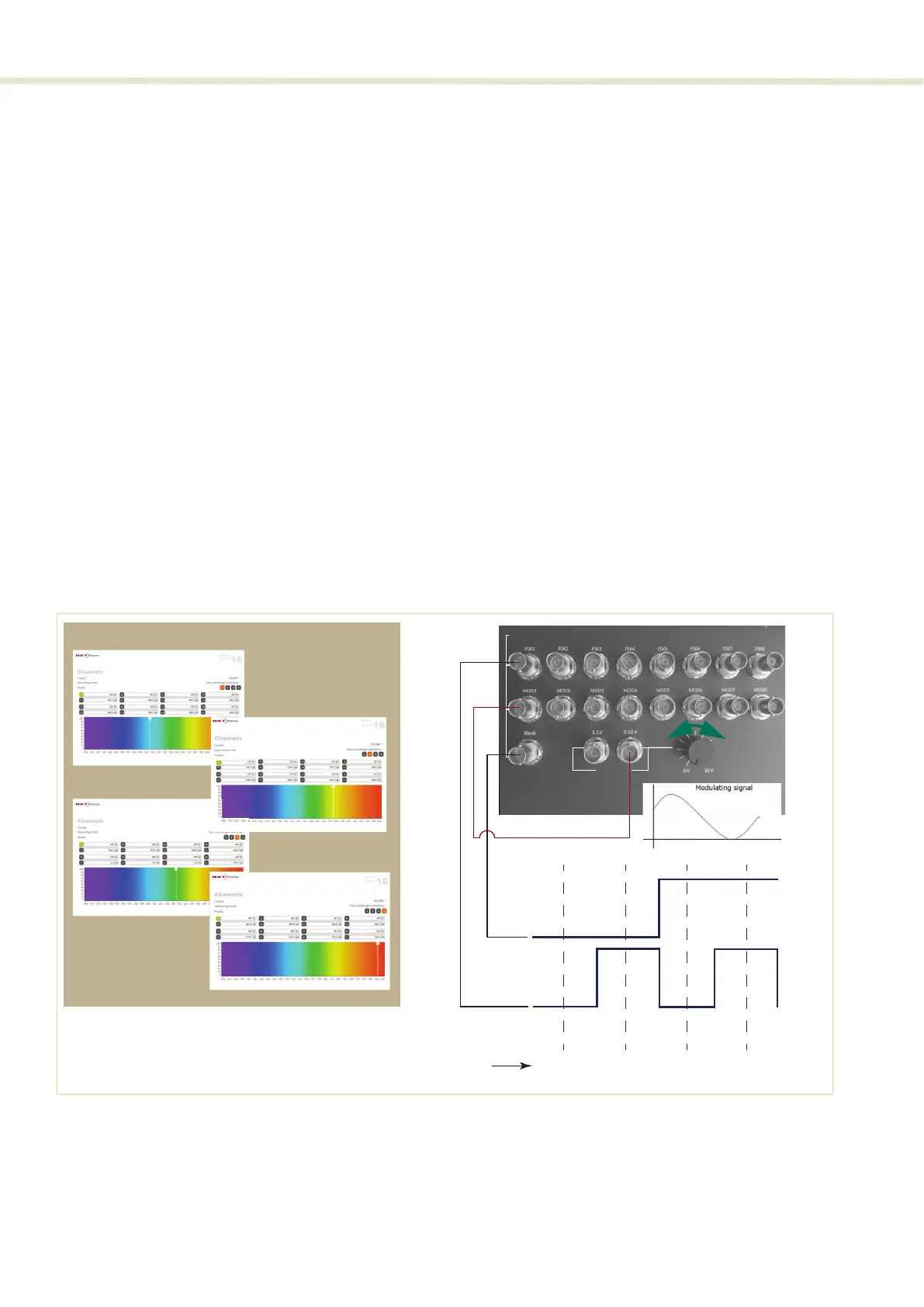
To modulate the amplitude of selected channels, a modulating signal can be
connected to the MOD1-8 signals (i.e. instead of them being pulled high). For
four-channel or four-profile FWS configurations only MOD1 is connected to a
varying signal to modulate the channels. Use MOD1 to MOD8 as needed to
modulate channels in a 16-channel FWS configuration.
Modulation amplitude
CONTROL must be configured for the modulation signal range. See“VIS/NIR or
NIR/IR modulation gain” on page 48.
Simulate modulation
1. Using a 4-channel FWS configuration, connect the 0-10 V output pin of the
COMMAND to MOD1 instead of the +3.3 V output.
2. Set the modulation gain in the Setup page to the 0-10 V range (see“VIS/NIR
or NIR/IR modulation gain” on page 48.
3. With the system running, vary the voltage of the 0-10 V pin using the
adjustment knob next to the pin.
4. Observe that the output emission level varies directly with the 0-10 V output
pin voltage.
Figure 51 Fast wavelength switching: simulated modulated 4 λ setup
Wavelengths 1 to 4 Selectionin
Blankin
Test
Outputs
CONTROL Channel/Prole
ch1 - prole 3
ch1 - prole 4
AOTF channel selected
ch1
prole 1
ch1
prole 2
ch1
prole 3
ch1
prole 4
V+
0V
V+
0V
FSK1in
Blankin
MOD1in
Signals
ch1 - prole 1
ch1 - prole 2
0V
10V