Electrical Connections
36
Figure 20 Connecting a SELECT - dual ERD
3. Using the other External bus cable, connect the Bus Through connector of
the SELECT (item C of Figure 20) to the Bus Input connector of ERD 1 (item B
of Figure 21).
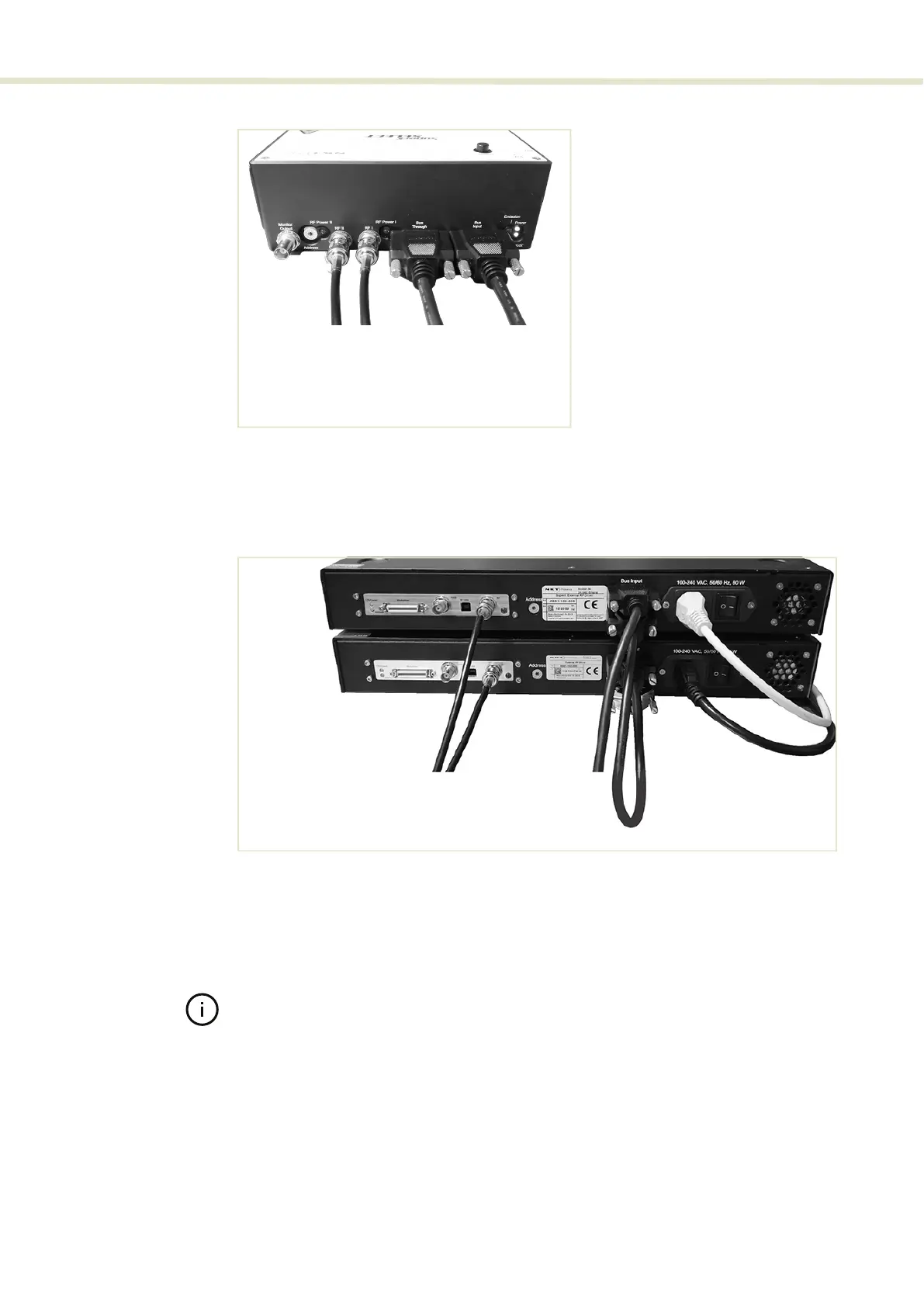
Figure 21 Connecting dual ERDs
4. Connect the Bus Through connector of ERD 1 to the Bus Input connector of
ERD 2 (item D of Figure 21).
5. Place the bus defeater (Figure 18) onto the Bus Through connector of the
ERD (item E of Figure 21).
Note: Ensure to terminate the External bus with an NKT Photonics bus defeater,
Without the bus defeater, the interlock circuit remains open disabling laser emis-
sion.
6. Using an RF coaxial cable, connect the RF BNC port of the ERD 1 (item A of
Figure 21) to the RF 1 port of the SELECT (item B of Figure 20).
7. Using the other RF coaxial cable, connect the RF BNC port of the ERD 2 (item
B of Figure 21) to the RF 2 port of the SELECT (item A of Figure 20).
A
B
C
A: RF2
from RF
out ERD2
B: RF1
from RF
out ERD1
C: Bus Through to External BUS
ERD1
D: Bus Input from External BUS
SuperK laser
D
A B
C
D
A: RF
ERD1
to RF1
Select
B: RF
ERD2
to RF2
Select
C: External bus
from Select
D: External bus
ERD1 to ERD2
E: Bus defeater
ERD2 bus thr.
E
ERD 1
ERD 2