NORDAC LINK (SK 250E-FDS ... SK 280E-FDS) – Users Manual for Frequency Inverters as Field Distributors
144 BU 0250 en-3021
Pos: 458 /Anleitungen/ Elektronik/F U und Starter/5. Parameter/ Parameterauflis tung (P000 ...)/P500- P599/Parameter P541 – Rel ais und digitale Ausgänge se tzen [SK 2xxE, SK 2xxE-FDS] @ 2\mod _1346932170278_388. docx @ 43248 @ @ 1
P541
Set relay
(set digital output)
S
0000 ... FFF (hex)
{ 0000 }
This function provides the opportunity to control the relay and the digital outputs independently of
the frequency inverter status. To do this, the relevant output must be set to the function "External
control".
This function can either be used manually or in combination with a bus control.
Bit 0 =
Digital output 1
Bit 6 =
Bus/An/Dig Out Bit 5,
“Bus/Analogue /Digital Out Bit 5”
Bit 1 =
Bus/AS-i Out Bit 0
Bit 7 =
Bus digital output 7
Bit 2 =
Bus/AS-i Out Bit 1
Bit 8 =
Bus digital output 8
Bit 3 =
Bus/AS-i Out Bit 2
Bit 9 =
Bus statusword Bit10
Bit 4 =
Bus/AS-i Out Bit 3
Bit 10 =
Bus statusword Bit13
Bit 5 =
Bus/An/Dig Out Bit 4,
“Bus/Analogue /Digital Out Bit 4”
Bit 11 =
Digital output 2
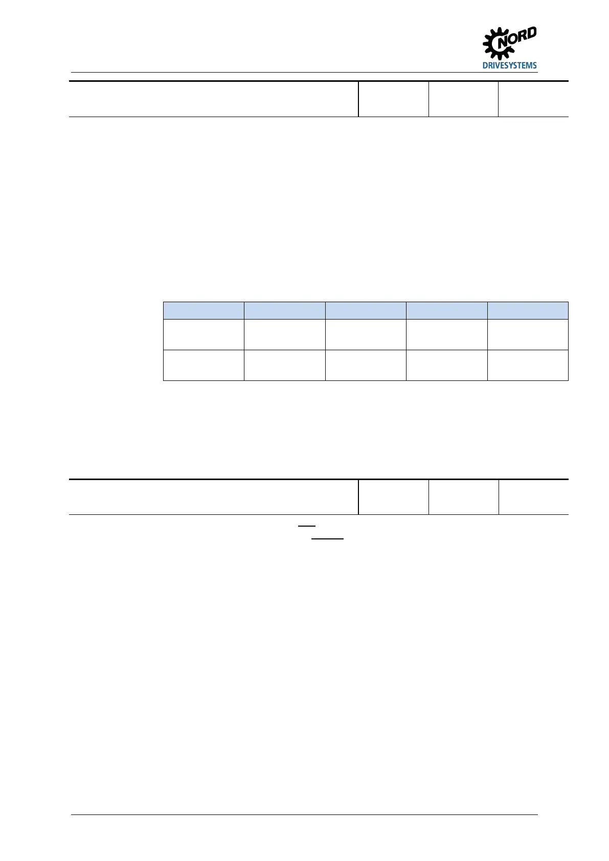
Bits 8-11 Bits 7-4 Bits 3-0
Min. value
0000
0
0000
0
0000
0
Binary
hex
Max. value
1111
F
1111
F
1111
F
Binary
hex
Changes which are made to the settings are not saved in the EEPROM. After "Power ON" of the
frequency inverter, the parameter is therefore in the default setting.
Setting of the value via …
BUS:
The corresponding hex value is written into the parameter, thereby setting the
relay and digital outputs.
SimpleBox: The hexadecimal code is entered directly when the SimpleBox is used.
ParameterBox: Each individual output can be separately called up in plain text and activated.
Pos: 459 /Anleitungen/ Elektronik/F U und Starter/5. Parameter/ Parameterauflis tung (P000 ...)/P500- P599/Parameter P542 – Ana logausgang setzen [SK 1 x0E, SK 2xxE, SK 2xxE-FDS] @ 2\mod_134693 2170902_388.doc x @ 43272 @ @ 1
P542 [-01]
[-02]
Set analogue output
(Set analogue output)
S
0.0 ... 10.0 V
{ all 0.0 }
only with
SK CU4-IOE or
SK TU4-IOE
[-01] = First IOE, AOUT of the first I/O extension (SK xU4IOE)
[-02] = Second IOE, AOUT of the second I/O extension (SK xU4IOE)
The analogue output of the FI can be set with this function, independently of the actual operating
state. To do this, the relevant analogue output must be set to the function "External control"
(P418 = 7).
This function can either be used manually or in combination with a bus control. The value set here
will, once confirmed, be produced at the analogue output.
Changes which are made to the settings are not saved in the EEPROM. After "Power ON" of the
frequency inverter, the parameter is therefore in the default setting.
Pos: 460 /Allgemein/A llgemeingültige Module/---------Seitenumbruch kompakt --------- @ 13\mod_14763696959 06_0.docx @ 2265495 @ @ 1

 Loading...


