POSICON positioning control – Supplementary manual for series SK 200E and SK 250E-FDS
16 BU 0210 en-3117
Pos: 44 /A nl eitu nge n/El ek tro nik/FU u nd S tart er/ 2. M o ntag e un d Ins tall ati on/ El ektri sc her Ansc hlus s/S K 1xx E, SK 2x xE, S K xxxE-FD S/St euert eil/De tails St euer anschl üsse (S amml ung)/ Detail s Ste uerans chlüss e_0 0_Tabel len kopf_[ SK 1xx E, SK 2x xE] @ 7\mod_1435561812889_388.docx @ 228818 @ @ 1
Description / Technical data
Designation Meaning No. Function of factory setting
Pos: 45 /Anlei tunge n/Ele ktro nik/FU und Start er/2. Mont age und Ins tall ation/ Ele ktrisc her Ansc hluss /SK 1 xxE, SK 2x xE, SK xx xE-FD S/St euer tei l/D etail s Ste uer ansc hlüs se ( Sa mmlu ng) /De tail s St euer ans chl üss e_ 03_D IN [ SK 2xxE] @ 7 \mod_1435562625904_388.docx @ 229010 @ @ 1
Actuation of device via an external controller, switch or the like, connection of HTL
transmitter (DIN2 and DIN3 only)
as per EN 61131-2, type 1
Low: 0-5 V (~ 9.5 kΩ)
High: 15-30 V (~ 2.5 - 3.5 kΩ)
Scan time: 1 ms
Reaction time: 4 - 5 ms
Input capacitance
10 nF (DIN1, DIN 4)
1.2 nF (DIN 2, DIN 3)
DIN 2 and DIN 3 double allocation
Min.: 250 Hz, Max.: 205 kHz
DIN2 Digital input 2 P420 [-02] ON left
DIN4 Digital input 4 P420 [-04] Fixed frequency 2 ( P465[-02])
Pos: 46 /Anlei tunge n/Ele ktro nik/FU und Start er/2. Mont age und Ins tall ation/ Ele ktrisc her Ansc hluss /SK 1 xxE, SK 2xxE, S K xxxE-FD S/St euert eil/D etails Steuer ansc hlüss e (Sam mlung) /Detai ls Ste uerans chl üsse_ 05_Qu elle St euers pann ung [SK 1 xxE, SK 2 x0E] @ 7\ mod_1435561830830_388.docx @ 228882 @ @ 1
Control voltage of device, e.g. for supplying accessories.
24 V DC ± 25 %, short circuit-proof
GND / 0V Reference potential GND - -
See "Total currents" information (
Pos: 47 /A nl eitu nge n/El ek tro nik/FU u nd S tart er/ 2. M o ntag e un d Ins tall ation/ Ele ktrisc her Ansc hluss /SK 1 xxE, SK 2x xE, SK xx xE-FD S/Steu ertei l/De tails St euer anschl üsse (S ammlu ng)/D etail s Steuer ans chlüss e_0 7_SYS [S K 1x0E, SK 2xxE] @ 7\mod_1435563267345_388.docx @ 229362 @ @ 1
NORD-specific bus system for communicating with other devices (e.g. intelligent
option modules or frequency inverter)
Up to four frequency inverters (SK 2xxE,
SK 1x0E) can be operated on a single
system bus.
Address = 32 / 34 / 36 / 38
dec
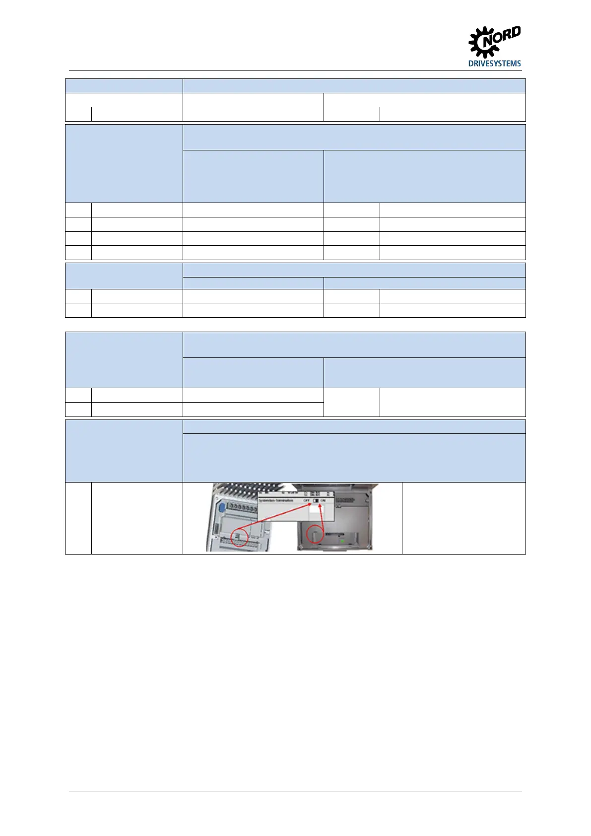
Pos: 48 /Anlei tunge n/Ele ktro nik/FU und Start er/2. Mont age und Ins tall ation/ Ele ktrisc her Ansc hluss /SK 1 xxE, SK 2x xE, SK xx xE-FD S/Steu ertei l/De tails St euer anschl üsse (S ammlu ng)/D etail s Steuer ans chlüss e_0 7_SYS _Ergä nzung_ Absc hluss wider stan d [SK 1x0 E, SK 2x xE] @ 7\mod_1435563760874_388.docx @ 229394 @ @ 1
resistance
Termination at the physical end of the bus system
If the device is supplied preassembled (e.g. equipped with customer unit SK CU4 / SK TU4) the terminating
resistors on the device and the module are factory-set. If other devices are going to be incorporated in the
system bus, the terminating resistors must be reset accordingly. It must always be checked before
commissioning that the terminating resistors have been correctly set (1x at beginning and 1x at end
of system bus).
(For deviating factory setting, see
explanation above)
Pos: 49 /A llg em ein/ Allg em eing ülti ge M od ule/ ---------Seite numbruc h kom pakt --------- @ 13\ mod_1476369695906_0.docx @ 2265495 @ @ 1
 Loading...


