Kronos Series 3
10
2 Installation
2.1 Rear Panel
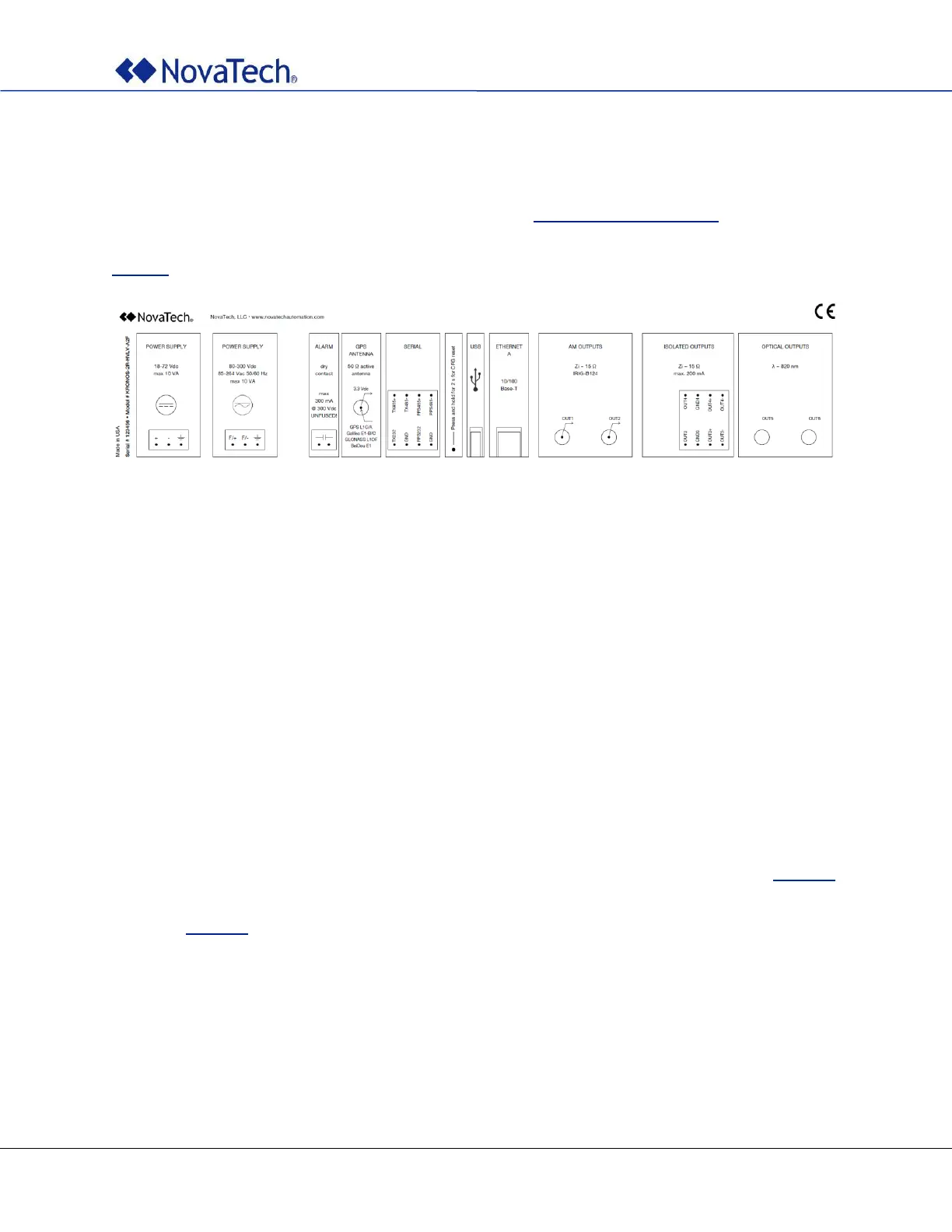
Refer to your clock’s part number and to the information in Appendix A – Options List to determine the
configuration. The label on the top cover of the clock always reflects the particular configuration of the clock
and can be used to determine the correct allocation of all connectors and signals. See also example in
Figure 1.
Figure 1: Label with configuration
2.2 Mounting
Kronos clocks are designed to be mounted in a 19” rack using four M6x15 screws (not included).
2.2.1 Clearances
Allow adequate clearance for all connections on the rear panel. Make sure that the clearances provided for
the antenna cable respect the specified minimum bending radius. Minimum bending radius depends on the
cable used. See cable specifications for details.
Note: If the minimum bending radius of the antenna cable is not observed, its impedance might
be altered which may compromise the unit’s performance.
2.2.2 Environment
Note: Make sure that temperatures inside the cabinet do not exceed the limits stated in Table 35.
Appropriate heating or cooling measures must be provided to guarantee that this
requirement is met at all times. Also, air humidity should comply with the limits described
in Table 35.