5238-E P-252
SECTION 10 COORDINATE SYSTEM CONVERSION
2. Conversion Format
The radius vector and C-axis angle after coordinate conversion are calculated with the formula
below.
LE33013R0301200020001
3. Program Examples
G137 is effective until G136 is designated. Do not designate other commands in the G136 block.
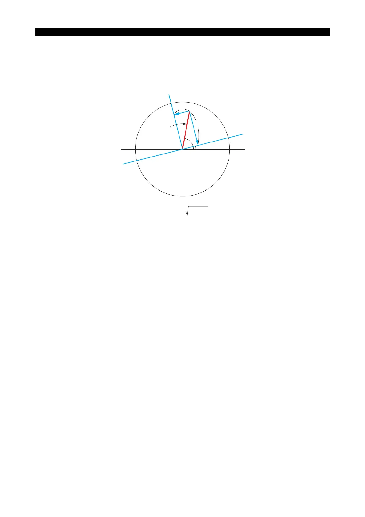
For the C command in a G137 block, designate the angle in reference to the C-axis zero point. This
angle is equivalent to "θ" in the figure in 2. "Conversion Format" above.
After designation of G137, use X and Y words instead of X and C words as positioning commands
until G136 is designated.
Example 1: Fixed cycle machining at P
1
LE33013R0301200030001
θ
C = 0°
+Y
+X
X
Y
C
X′
Radius vector, X′ =
X
2
+ Y
2
Angle, C = tan
-1
(Y/X) + θ
N01
N02
N03
N04
G137
G181
G180
G136
C20
X10 Y50 Z125 Q2 F30 K10