16
Chapter 2 Nomenclature and Functions
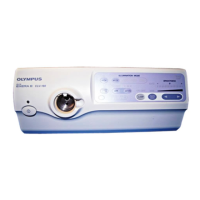
EVIS EXERA II VIDEO SYSTEM CENTER CV-180
1. Power switch
Press to turn the video system center ON or OFF.
2. Power indicator
Lights up when the video system center is ON.
3. Video connector socket
The video plug of the videoscope cable, videoscope or camera head are
connected to this socket.
4. Locking lever
Press down to disconnect the video plug of the videoscope cable,
videoscope or camera head.
5. Image source buttons
Press these buttons to select the image sources to be displayed on the
monitor. Press and hold the buttons to change (except “SCOPE”).
“Image source buttons” on page 62
6. Picture in picture (PinP) button
Press to display an image of the connected ancillary equipment and the
endoscopic live image together on the monitor.
• Setting of the PinP function
“PinP (picture in picture) function” on page 246
• Operation of the PinP function
“PinP (picture in picture) display” on page 64
7. White balance (Wh/B) button
Press to perform the white balance adjustment.
Section 4.5, “White balance adjustment” on page 52
8. White balance (Wh/B OK) indicator
The indicator lights up when the white balance adjustment is completed.
9. HDTV indicator
Lights up green when the instrument is turned ON, and turns white when the
HDTV compatible endoscope is connected to this instrument.
10. NBI indicator
Lights up green when the NBI compatible endoscope is connected to this
instrument, and turns white during NBI observation. This indicator works
only when the light source CLV-180 is used.
“NBI (narrow band imaging)” on page 151
Button The image on the monitor
SCOPE The endoscopic live image
DV/VCR The image of the videocassette recorder, etc.
PC The image of the image filing system
PRINTER The image of the video printer
 Loading...