CHAPTER 7 CALIBRATION
E5CK
7–6
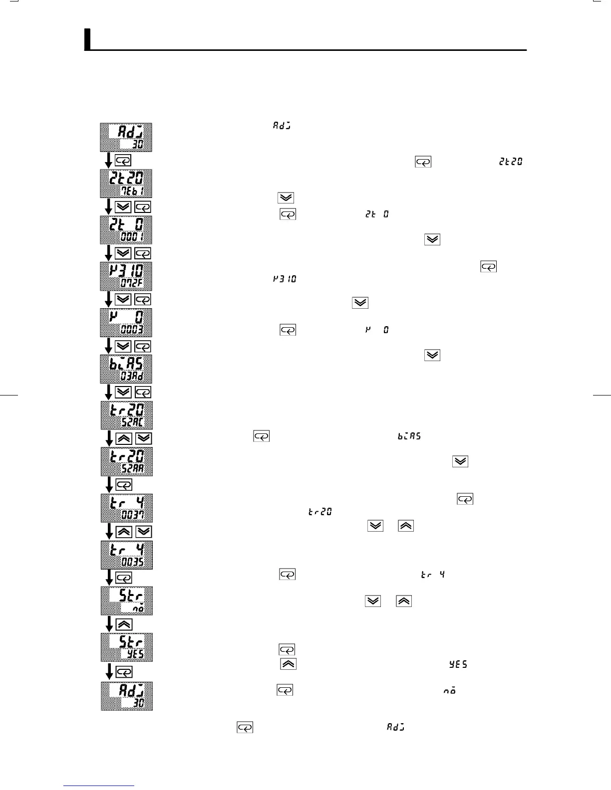
This example describes how to calibrate a thermocouple when the transfer
output function is supported. If the transfer output function is not supĆ
ported, skips steps (7) to (10).
(1) When [ĂĂ
] is displayed, the 30Ćminute timer is displayed on the
No.2 display and counts down. This timer serves as a guide for the agĆ
ing time when aging is required.
(2) First, calibrate the main input. Press the
key to display [ ]
(20 mV calibration display). Set STV output to 20 mV. When the value
on the No.2 display has stabilized (changes of several digits max.),
press the
key to temporarily store the calibration data.
(3) Press the
key to display [ ] (0 mV calibration display). Set
STV output to 0 mV. When the value on the No.2 display has stabilized
(changes of several digits max.), press the
key to temporarily
store the calibration data.
(4) Next, calibrate the cold junction compensator. Press the
key to
display [
] (310 mV calibration display). Set STV output to 310
mV. When the value on the No.2 display has stabilized (changes of sevĆ
eral digits max.), press the
key to temporarily store the calibraĆ
tion data.
(5) Press the
key to display [ ] (0 mV calibration display). Set
STV output to 0 mV. When the value on the No.2 display has stabilized
(changes of several digits max.), press the
key to temporarily
store the calibration data.
(6) Finally, calibrate the bias compensation value. Disconnect the STV,
and enable the thermocouple of the cold junction compensator. When
carrying this out, make sure that the wiring on the STV is disconĆ
nected.
Make sure that the cold junction compensator is set to 0C and press
the
key. The display changes to [ ] (calibration display for
the bias compensation value). When the value on the No.2 display has
stabilized (changes of several digits max.), press the
key to tempoĆ
rarily store the calibration data.
(7) Next, calibrate the transfer output function. If the transfer output
function is not supported, skip to step (11). Press the
key. The disĆ
play changes to [ ] (20 mA calibration display).
(8) Set the output to 20 mA by the or keys while monitoring the
voltage on the digital multimeter. In the example on the left, the disĆ
play indicates that the value two digits smaller than before calibraĆ
tion is 20 mA".
(9) Press the
key. The display changes to [ ] (4 mA calibration
display).
(10) Set the output to 4 mA by the
or keys while monitoring the
voltage on the digital multimeter. In the example on the left, the disĆ
play indicates that the value two digits smaller than before calibraĆ
tion is 4 mA".
(11) Press the
key until the display changes to the data store display.
Press the key. The No.2 display changes to [ ], and two seĆ
conds later the calibration data is stored to internal memory. If you
press the
key when the No.2 display reads [ĂĂĂ ], the calibration
data is disabled.
(12) This completes calibration of the thermocouple 2 group. Press the
key to return the display to [ĂĂĂ ].
F Calibration: ther-
mocouple 2