E5CK
II
JMeanings of Abbreviations
Sometimes the following abbreviations are used in parameter names, figures and in text exĆ
planations. These abbreviations mean the following:
Symbol Term
PV Process value
SP (Present) set point *1
LBA Loop break alarm
AT AutoĆtuning
EU Engineering unit *2
*1 In program pattern diagrams, the present SP is indicated.
*2 C, m, g and other units are indicated for scaled data. However, EU" is used as the minimum
unit for the data. For example, for 50.02 (m)", 1EU is taken as the minimum unit 0.01 (m).
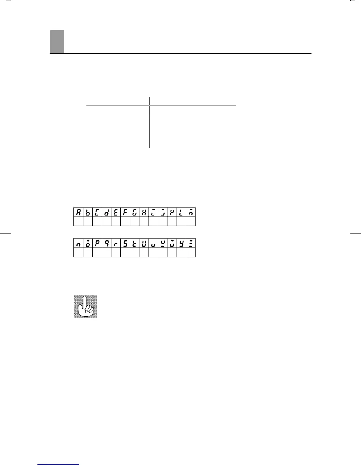
JHow to Read Display Symbols
The following tables show the correspondence between the symbols displayed on the displays
and alphabet characters.
ABCDEF GHI J KL M
NOPQRSTUVWXYZ
J“Reference” mark
This mark indicates that extra, useful information follows, such as supplementary explanations
and how to apply functions.
Conventions Used in This Manual