7.3 Calibrating Platinum Resistance Thermometers
E5CK
7–7
7.3 Calibrating Platinum Resistance Thermometers
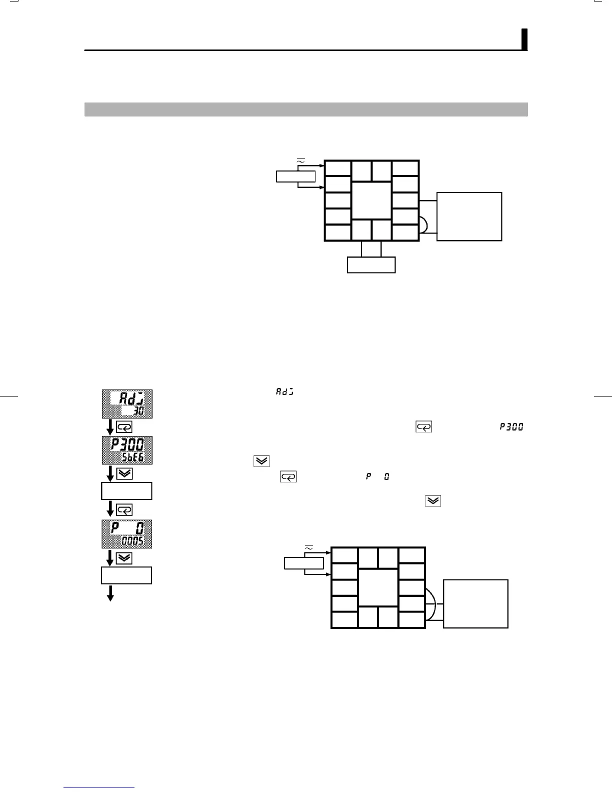
F Preparation
AC100-240V
(AC/DC24V )
~
10
9
8
7
6
5
4
3
2
1
1413
1211
DMM
6-dial
SOURCE
Ă• Use leads of the same thickness when connecting to the platinum resisĆ
tance thermometer.
Ă• In the above figure, 6Ćdial refers to a precision resistance box, and DMM
stands for a digital multimeter. However, note that the DMM is required
only when the transfer output function is supported.
Ă• Connect (short) the leads from terminal Nos.6 and 7.
This example describes how to calibrate a platinum resistance thermomeĆ
ter when the transfer output function is supported. If the transfer output
function is not supported, skips steps (7) to (10).
(1) When [ĂĂĂ
] is displayed, the 30Ćminute timer is displayed on the
No.2 display and counts down. This timer serves as a guide for the agĆ
ing time when aging is required.
(2) First, calibrate the main input. Press the key to display [ ]
(300Ω calibration display). Set the 6Ćdial to 300Ω. when the value on
the No.2 display has stabilized (changes of several digits max.), press
the
key to temporarily store the calibration data.
(3) Press the key to display [ ] (0Ω calibration display). Short
terminal Nos.6 to 8. When the value on the No.2 display has stabilized
(changes of several digits max.), press the
key to temporarily
store the calibration data.
(4) Next, calibrate the BĆB' input. Change the wiring as follows:
10
9
8
7
6
5
4
3
2
1
1413
1211
6-dial
AC100-240V
(AC/DC24V )
~
SOURCE
Make the connection across terminal Nos.6 and 7 and the 6Ćdial as
short as possible. Short terminal Nos.6 and 8.
F Calibration
Cont’d on next page
Change wiring.
Short terminal
Nos.6 to 8