CHAPTER 8 TROUBLESHOOTING
E5CK
8–2
8.1 Initial Checks
If trouble occurs, first of all check the following:
(1) Power supply
Make sure that the power supply is ON. Also, make sure that the powĆ
er supply is within the rated voltage range.
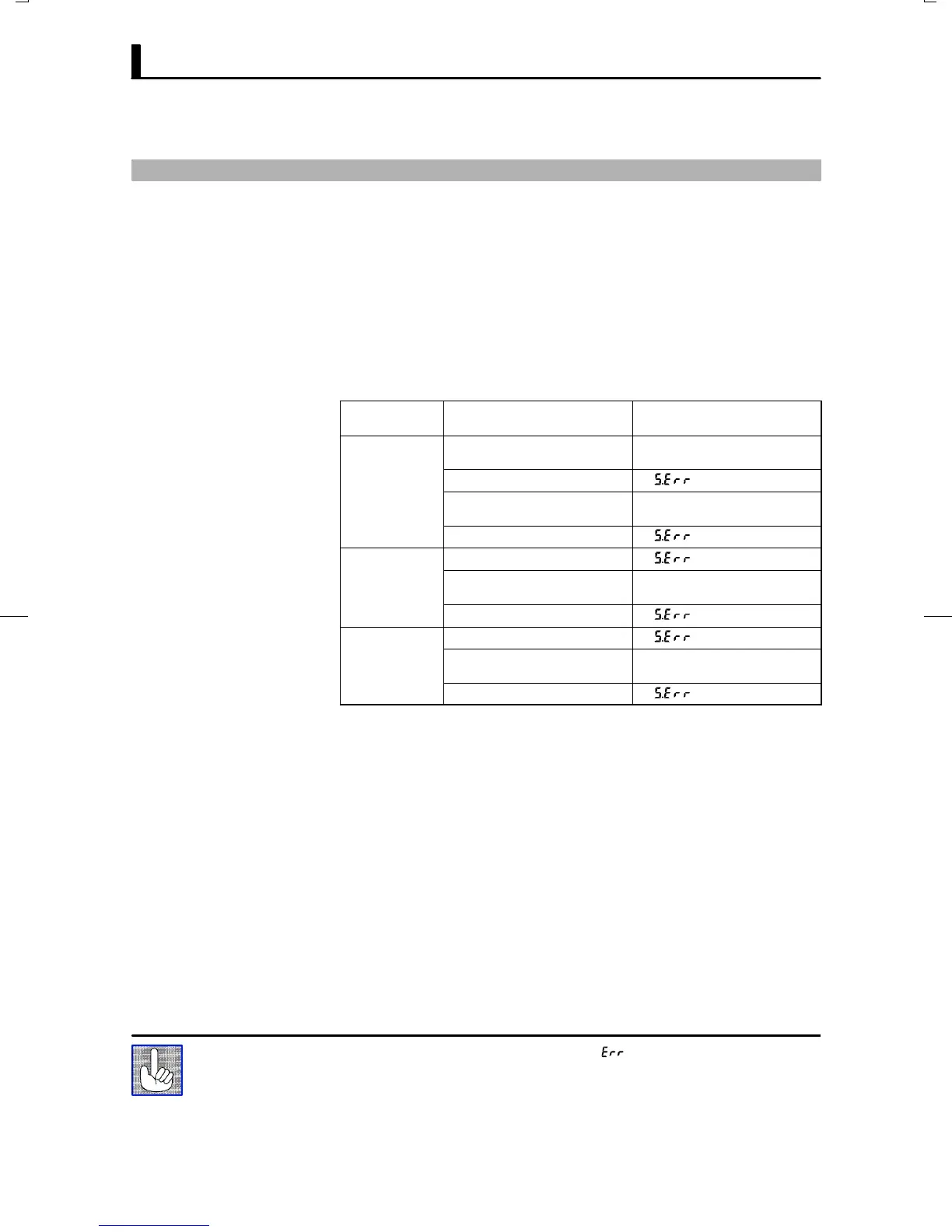
(2) Input type jumper
Make sure that the input type jumper is set to the correct input type.
The table below describes the operations when the jumper is not set
matched to the type of sensor connected to the input terminal.
Jumper
Setting
Parameter Operation
TC/PT
Current (0 to 20 mA) Operation is fixed at scaling lower
limit value.
Current (4 to 20 mA)
Voltage (0 to 10 V, 0 to 5 V) Operation is fixed at scaling lower
limit value.
Voltage (1 to 5 V)
I
Temperature input
Voltage (0 10 V, 0 to 5 V) Operation is fixed at scaling lower
limit value.
Voltage (1 to 5 V)
V
Temperature input
Current (0 to 20 mA) Operation is fixed at scaling lower
limit value.
Current (4 to 20 mA)
(3) Wiring
Make sure that all cables are properly connected.
(4) Communications conditions
When communicating via the RSĆ232C, RSĆ422 or RSĆ485 interfaces,
make sure that the baud rate and other communications condition
settings on the host computer and E5AKĆT controller are matching,
and are within the permissible ranges.
If there appears to be nothing wrong after checking the E5CKĆT controller,
and the same phenomenon continues, check the controller in more detail,
for example, on the error display.
If an error occurs during motor calibration, " is displayed on the No.2 display.
The following causes of errors are possible:
Ă• Control motor or potentiometer malfunction
Ă• Incorrect control motor or potentiometer wiring
Ă• Potentiometer is not connected
About Errors That
Occur During
Motor Calibration