CHAPTER 2 PREPARATIONS
E5CK
2–8
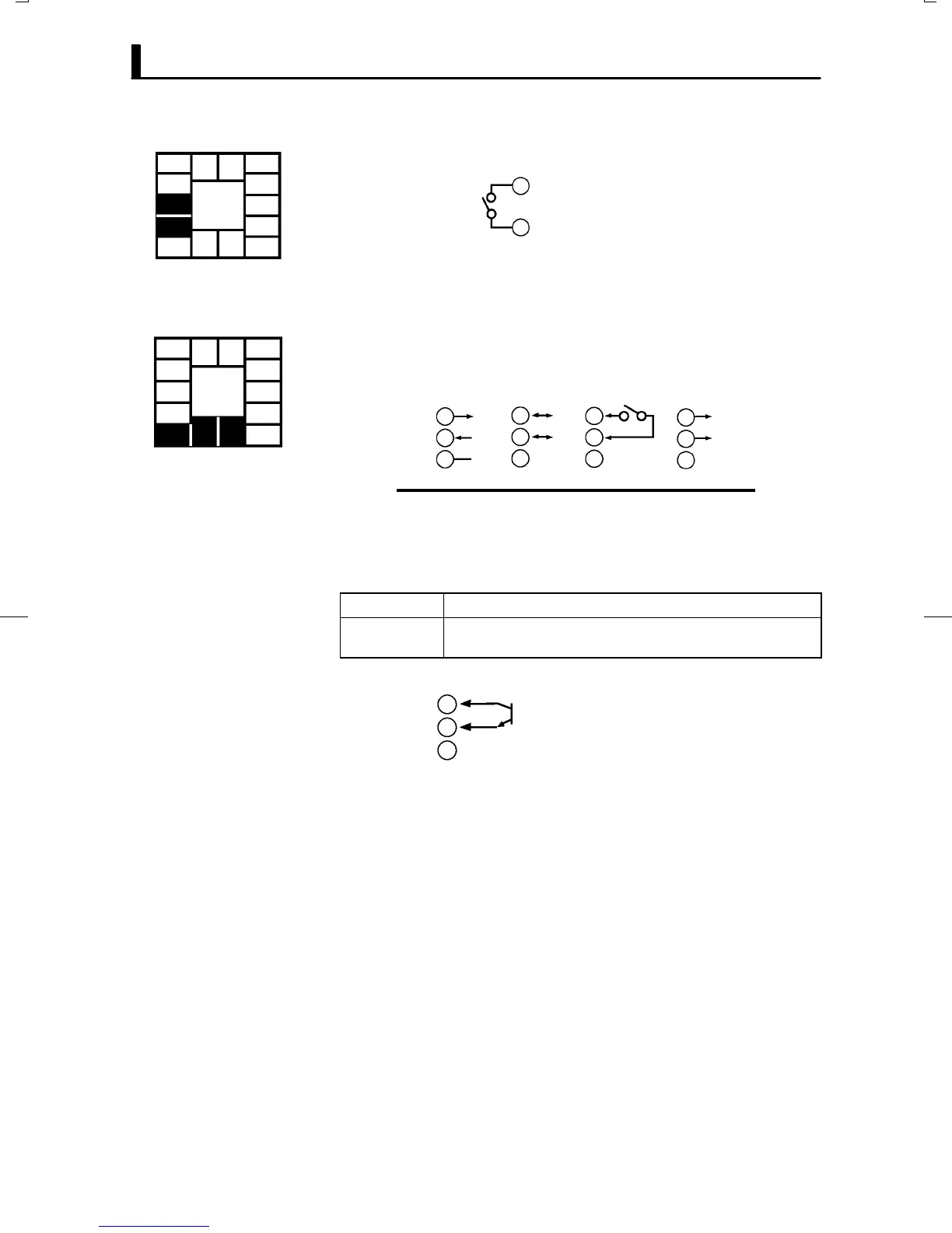
Ă• Terminal Nos.2 and 3 are for auxiliary output 1 (SUB1).
Ă• The internal equalizing circuit for auxiliary output 1 is as follows:
3
2
Ă• Relay specifications are as follows:
1a, 250 VAC, 1 A
Ă• Terminal Nos.1, 13 and 14 are available only for controllers that support
optional functions.
Ă• These terminals can be wired as follows depending on the controller
type.
13
14
1
13
14
1
13
14
1
13
14
1
SD
RD
SG
A
B
+
–
4 to 20mA
E53-CK01
RS-232C
E53-CK03
RS-485
E53-CKB E53-CKF
Event input Transfer output
Ă• For details on the RSĆ232C and RSĆ485 communications functions, see
Chapter 6, Using the Communications Functions.
Ă• Use event inputs under the following conditions:
Contact input ON: 1kΩmax., OFF: 100 kΩ max.
No-contact input ON: residual voltage 1.5 V max., OFF: leakage current 0.1 mA
max.
Polarities during noĆcontact input are as follows:
13
14
1
+
–
Ă• Transfer output specifications are as follows:
4 to 20 mA DC, Permissible load impedance: 500Ω max., Resolution:
Approx. 2600
F Auxiliary output 1
5
4
3
2
1
10
9
8
7
6
13 14
11 12
F Option
5
4
3
2
1
10
9
8
7
6
13 14
11 12