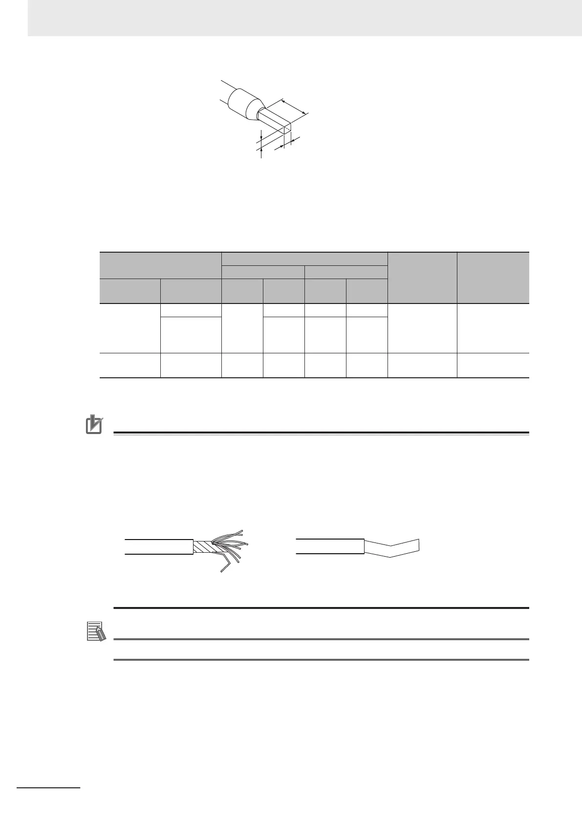
8 to 10 mm
2.4 mm max.
(Terminals other than ground terminals)
2.7 mm max.
(Ground terminals)
1.6 mm max.
(Terminals other than ground terminals)
2.0 mm max.
(Ground terminals)
l
Using Twisted or Solid Wires
If you use twisted wires or solid wires, use the following table to determine the correct wire specifi-
cations.
Terminals
Wire type
Wire size
Conductor
length
(stripping
length)
Twisted wires Solid wire
Classification
Current ca-
pacity
Plated
Unplat-
ed
Plated
Unplat-
ed
All terminals
except ground
terminals
2 A max. Possible Possible Possible Possible
0.08 to 1.5 mm
2
(A
WG 28 to 16)
8 to 10 mm
Greater than 2
A and 4 A or
less
Not pos-
sible
Possible
*1
Not pos-
sible
Ground termi-
nals
--- Possible
Possible Possible Possible
2.0 mm
2
10 to 12 mm
*1. Secure wires to the screwless clamping terminal block. Refer to Securing Wires on page
5-57 for how to secure
wires.
Precautions for Correct Use
• Use cables with suitable wire sizes for the carrying current. There are also restrictions on the
current due to the ambient temperature. Refer to the manuals for the cables and use the ca-
bles correctly for the operating environment.
• For twisted wires, strip the sheath and twist the conductor portion. Do not unravel or bend the
conductor portion of twisted wires or solid wires.
Unravel wires Bend wires
NG NG
Additional Information
If more than 2 A will flow on the wires, use plated wires or use ferrules.
5 Installation and Wiring
5-54
NX-series NX1P2 CPU Unit Hardware User’s Manual (W578)
 Loading...


