Appendix BSpecifications
148
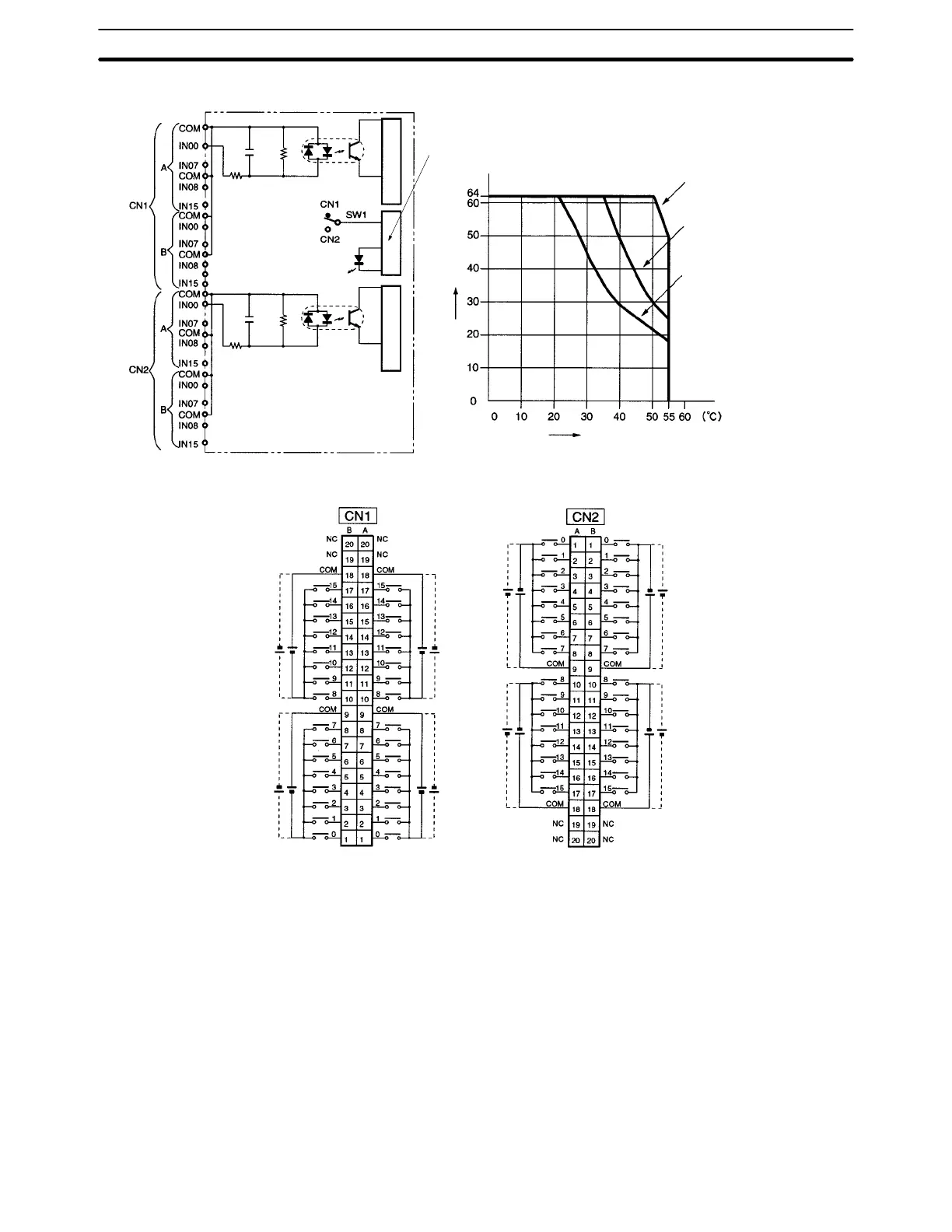
Circuit Configuration
to
to
to
to
to
to
to
to
0.01 µF
470 Ω
3.9 kΩ
0.01 µF
470 Ω
3.9 kΩ
Input LED indicator
Internal circuitInternal circuit
Input LED indicator
Ambient Temperature for Simultaneously ON Points
Simultaneously ON points
Input voltage: 20.4 VDC
Input voltage: 24.0 VDC
Input voltage: 26.4 VDC
Ambient temperature
Terminal Connections
(m = 030 + 2 × I/O number)
(m + 1) words (m + 1) words (m + 2) words (m + 3) words
24 VDC
24 VDC
24 VDC
24 VDC
24 VDC
24 VDC
24 VDC
24 VDC
Note 1. The polarity of the input power supply can be either positive or negative. The polarity of all commons for
CN1 and CN2, however, must be the same.
2. COM terminals for CN1 and CN2 must all be wired even though they are connected internally.