5 - 31
5 Setup and Wiring
Vision System FH/FZ5 series Hardware Setup Manual (Z366)
5-5 Camera Installation
5
5-5-2 FH-1000/FH-3000 Series
Ground
When the connected camera to the Sensor Control comes packaged with a base, make sure to
mount with the base.
Since the enclosure of the camera main
body made of metals is short-circuited with the internal
circuit, the internal circuit might be short-circuited with FG if no base is used, so that failures or
malfunctions may be caused.
Connection the FH-1000/FH-3000 series to the FH-SC12/FH-SM12 (12 megapixels)
When you connect FH-1000 series or FH-30
00 series to the FH-SC12/FH-SM12:
Do not ground the positive terminal of DC24V powe
r source. The internal circuit is possible to
be given damage, it can be cause the failure.
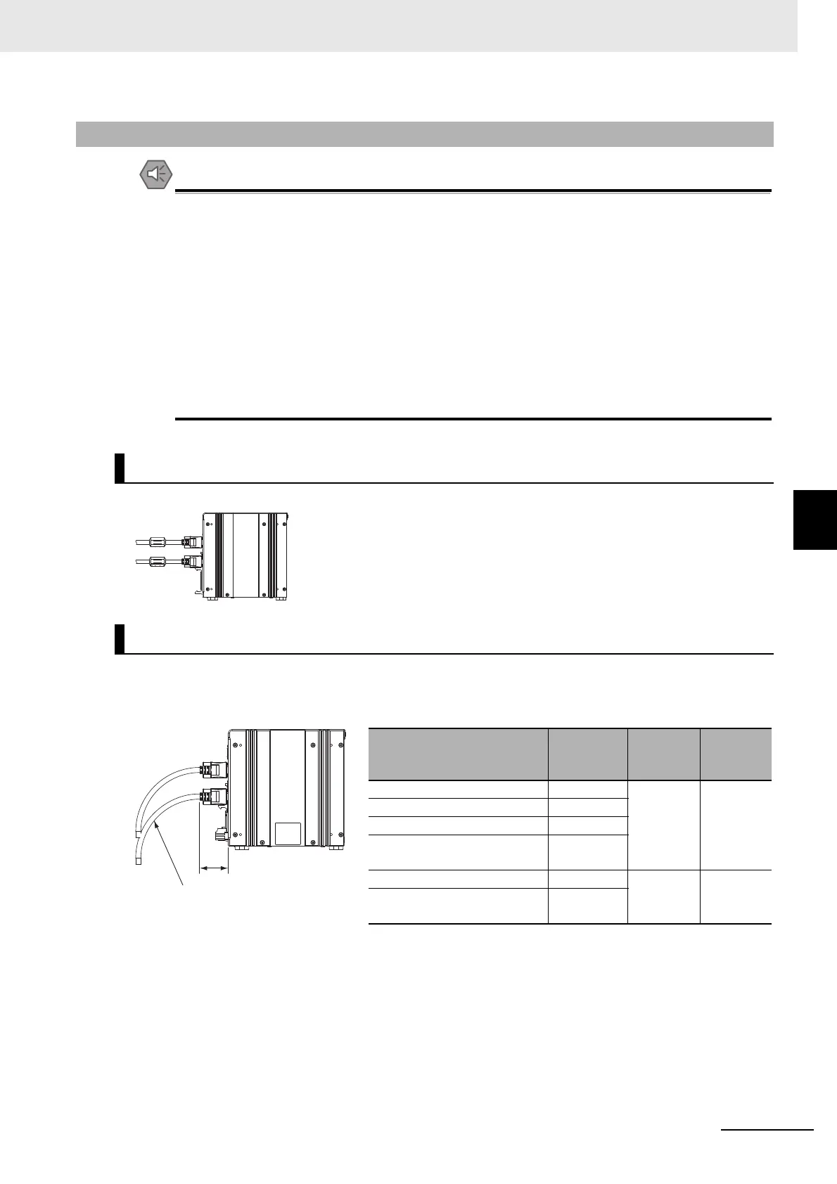
Mount the ferrite core attached to the camera cable to near the Sensor Controller.
When you connect the cable to the Sensor Controller, secure the minimum bending radius of the cable
or cable connector.
5-5-2 FH-1000/FH-3000 Series
Mounting of Ferrite core
Camera cable mounting
Minimum
bending radius
Connector length
Name Model
Minimum
bending
radius
Connector
length
Camera Cable FZ-VS3 69 mm 30 mm
Right-angle Camera Cable FZ-VSL3
Bend resistant Camera Cable FZ-VSB3
Bend resistant Right-angle
Camera Cable
FZ-VSLB3
Long-distance Camera Cable FZ-VS4 78 mm 42 mm
Long-distance Right-angle
Camera Cable
FZ-VSL4

 Loading...

