6 I/O Interface
6 - 4
Vision System FH/FZ5 series Hardware Setup Manual (Z366)
[Input]
Applicable signals/
• No.4 to 6, 9 to 11 pins:
Connect the COMIN1 terminal wh
en using these signals.
• No.7, 8, 12, 13 pins:
Connect the COMIN0 terminal wh
en using these signals.
[Output]
Applicable signals/
• No.15 to 19 pin, No.28 to 32pin:
Connect the COMOUT0 terminal when using these signals.
• No.48 to 57 pins:
Connect the COMOUT2 terminal when using these signals.
• No.58 to 66 pins:
Connect the COMOUT3 terminal when using these signals.
[Output]
Applicable signals/
• No.20 to 27 pins:
Connect the COMOUT1 and COMIN0 terminals when using these signals.
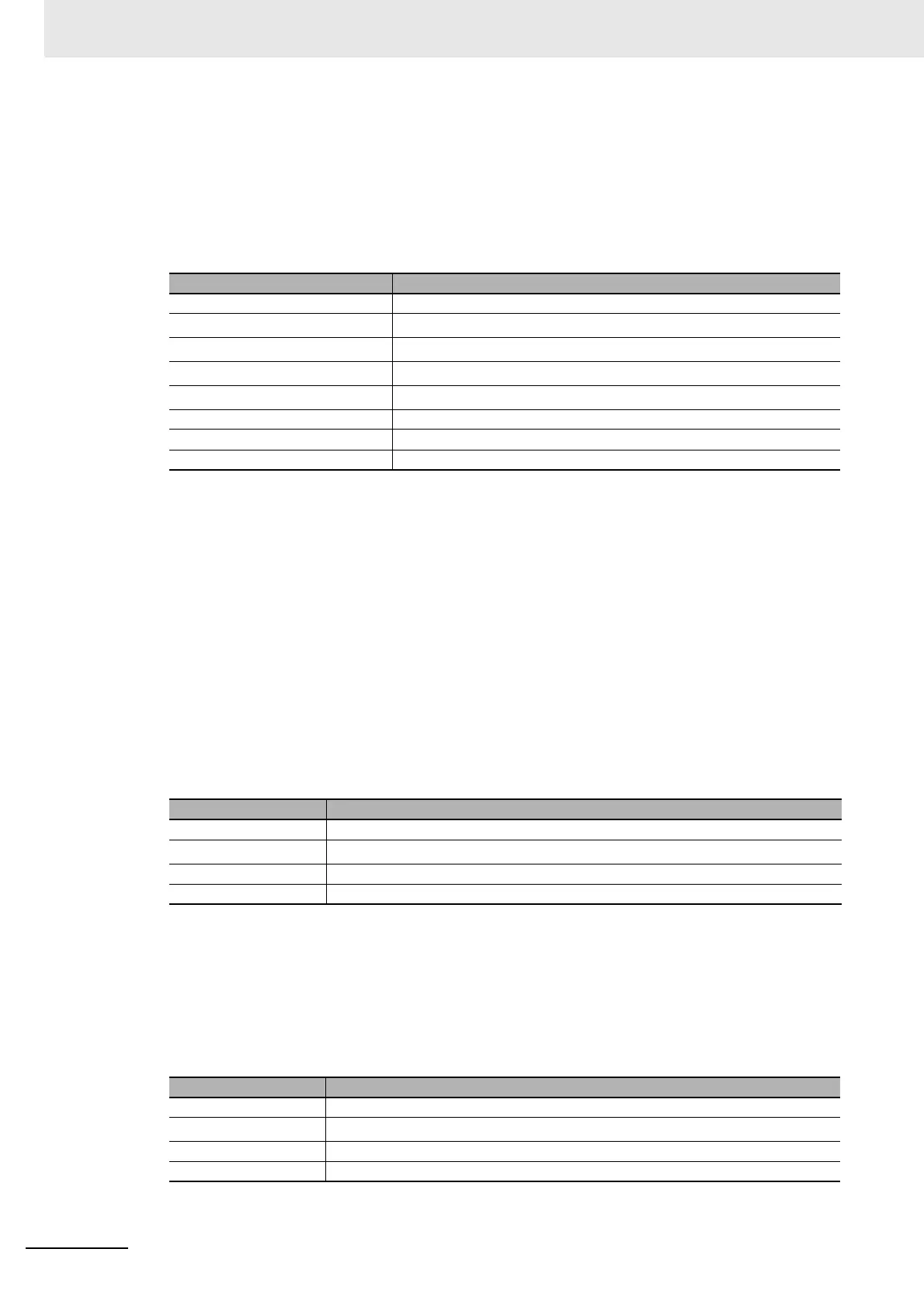
Item Specifications
Input voltage 12 to 24 VDC ±10%
ON current
*1
*1. ON current and ON voltage:
Those mean the current or voltage to turn ON from OF
F. The ON voltage value is the potential difference
between COMIN and each input terminal.
5 mA min.
ON voltage
*1
8.8 V min.
OFF current
*2
*2. OFF current and OFF voltage:
Those mean the current or voltage to turn OFF from ON
. The OFF voltage value is the potential difference
between COMIN and each input terminal.
0.5 mA max.
OFF voltage
*2
0.8 V max.
ON delay 0.1 ms max.
OFF delay 0.1 ms max.
Maximum frequency response 4 KHz
Item Specifications
Output voltage 12 to 24 VDC ±10%
Load current
*1
*1. The current value must be the specified load current or lower. Exceeding the specified current value may
cause damage of the output circuit.
45 mA max.
ON residual voltage 2 V max.
OFF leakage current 0.2 mA max.
Item Specifications
Output voltage 12 to 24 VDC ±10%
Load current
*1
*1. The current value must be the specified load current or lower. Exceeding the specified current value may
cause damage of the output circuit.
45 mA max.
ON residual voltage 2 V max.
OFF leakage current 0.2 mA max.

 Loading...

