6 I/O Interface
6 - 34
Vision System FH/FZ5 series Hardware Setup Manual (Z366)
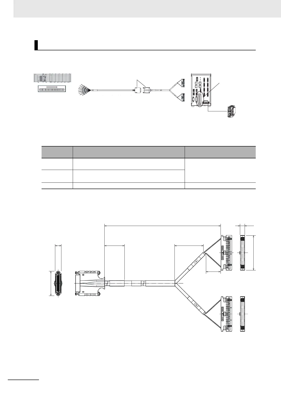
Connection Structure
Cable (FH-VPX-FZ)
FH-VPX-FZ
Connector
No.
Connection Destination Special Notes
CN1 Connect to the parallel port CN1 of the FH Sensor Con-
troller.
Even if you connect the revers CN1
a
nd CN2, Sensor Controller does
not perform.
It is immune to breakdown.
CN2 Connect to the parallel port CN2 of the FH Sensor Con-
troller.
CN3 Connect to the Parallel I/O cable FZ-VP.
PLC, terminal blocks or
other products
FZ-VP / FZ-VPX
CN3
CN1
CN2
FH-VPX-FZ
Power supply used
in the FH controller:
Power supply S8VS
series (24 VDC)
Parallel connector
(CN1/CN2)
FH controller
Connecting the FZ-VP and the FH-VPX-
* After the connection, lock it securely.
CN3
CN1
CN2
8
34
40
500
(35)
(20)
7
(Unit: mm)
47.8

 Loading...

