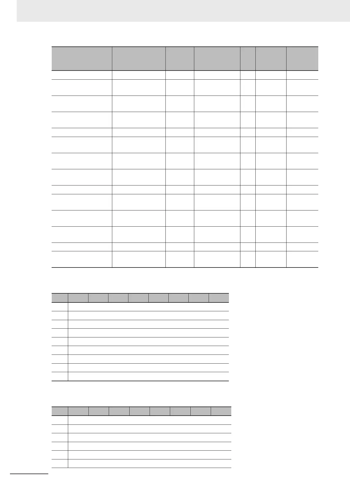
Data name Data type
Default
value
I/O port name Unit
Index
number
(hex)
Subindex
number
(hex)
: : : : : : :
Ch1 Analog Input Value
991-1000
ARRAY[0..9] OF INT 0 Ch1 Analog Input
V
alue 991-1000
--- 6001
67
Ch2 Analog Input Value
1-10
ARRAY[0..9] OF INT 0 Ch2 Analog Input
Value 1-10
--- 6002
04
Ch2 Analog Input Value
11-20
ARRAY[0..9] OF INT
0 Ch2 Analog Input
Value 11-20
--- 6002 05
: : : : : : :
Ch2 Analog Input Value
991-1000
ARRAY[0..9] OF INT 0 Ch2 Analog Input
Value 991-1000
--- 6002
67
Ch3 Analog Input Value
1-10
ARRAY[0..9] OF INT 0 Ch3 Analog Input
Value 1-10
--- 6003
04
Ch3 Analog Input Value
11-20
ARRAY[0..9] OF INT
0 Ch3 Analog Input
Value 11-20
--- 6003 05
: : : : : : :
Ch3 Analog Input Value
991-1000
ARRAY[0..9] OF INT 0 Ch3 Analog Input
Value 991-1000
--- 6003
67
Ch4 Analog Input Value
1-10
ARRAY[0..9] OF INT 0 Ch4 Analog Input
Value 1-10
--- 6004
04
Ch4 Analog Input Value
11-20
ARRAY[0..9] OF INT
0 Ch4 Analog Input
Value 11-20
--- 6004 05
: : : : : : :
Ch4 Analog Input Value
991-1000
ARRAY[0..9] OF INT 0 Ch4 Analog Input
Value 991-1000
--- 6004
67
The bit configuration of the Ch£ Analog Input Value 1-10 (ARRAY[0..9] OF INT) is given in the follow-
ing table.
Byte Bit 7 Bit 6 Bit 5 Bit 4 Bit 3 Bit 2 Bit 1 Bit 0
0
1st byte of Analog Input Value 1 in Ch£ Analog Input V
alue 1-10
+1
2nd byte of Analog Input Value 1 in Ch£
Analog Input Value 1-10
+2
1st byte of Analog Input Value 2 in Ch£
Analog Input Value 1-10
+3
2nd byte of Analog Input Value 2 in Ch£
Analog Input Value 1-10
+4
1st byte of Analog Input Value 3 in Ch£
Analog Input Value 1-10
+5
2nd byte of Analog Input Value 3 in Ch£
Analog Input Value 1-10
: :
+18
1st byte of Analog Input V
alue 10 in Ch£ Analog Input V
alue 1-10
+19
2nd byte of Analog Input V
alue 10 in Ch£ Analog Input Value 1-10
The bit configuration of the Ch£ Analog Input V
alue 1
1-20 (ARRA
Y[0..9] OF INT) is given in the fol-
lowing table.
Byte Bit 7 Bit 6 Bit 5 Bit 4 Bit 3 Bit 2 Bit 1 Bit 0
0
1st byte of Analog Input Value 11 in Ch£ Analog Input Value 11-20
+1
2nd byte of Analog Input V
alue 11 in Ch£ Analog Input Value 11-20
+2
1st byte of Analog Input V
alue 12 in Ch£ Analog Input Value 11-20
+3
2nd byte of Analog Input V
alue 12 in Ch£ Analog Input Value 1
1-20
+4
1st byte of Analog Input Value 13 in Ch£ Analog Input Value 11-20
+5
2nd byte of Analog Input V
alue 13 in Ch£ Analog Input Value 1
1-20
7 I/O Data and List of Settings
7 - 10
NX-series Analog I/O Units User’s Manual for High-speed Analog Input Units (W592)