To enable/disable the digital low-pass filter with the relevant bit, set the cutoff frequency in the Unit
operation settings to a value other than 0. If the cutoff frequency is set to 0, the digital low-pass
filter will not be enabled even if the relevant bit is set to enable.
The relevant bit is Ch£
Digital Low-pass Filter Disable. Refer to Ch
£
Operation Command on
page 7 - 11 for details on Ch£ Operation Command.
Attenuation Characteristics and Step Response Characteristics
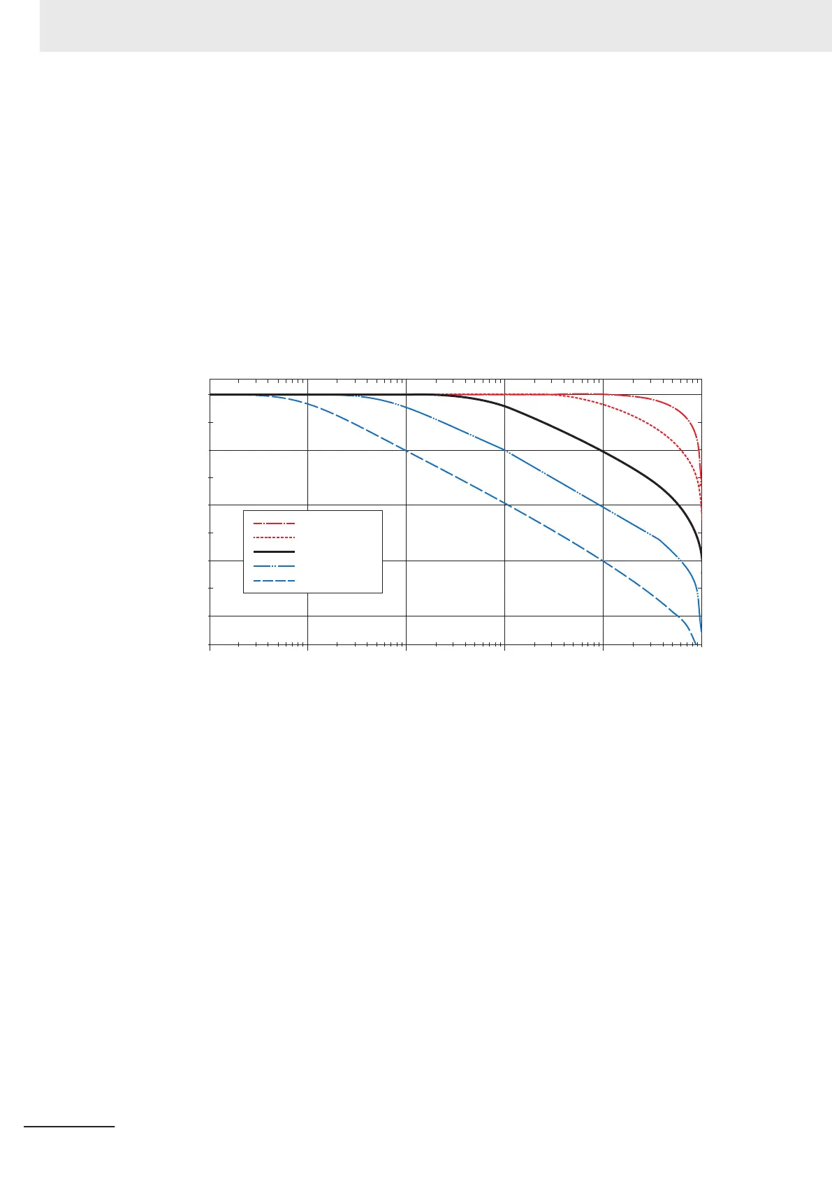
(a) Attenuation characteristics
The attenuation characteristics of the digital low-pass filter for typical cutoff frequencies are
shown below.
Input signals are attenuated by -3 dB with the cutof
f frequency. Note that the attenuation char-
acteristics shown in these graphs are based on theoretical values.
0
−10
−20
−30
−40
−50
-60
−70
-80
−90
1 10 100 1 k 10 k 100 k
fc = 50 kHz
fc = 10 kHz
fc = 1k Hz
fc = 100 Hz
fc = 10 Hz
Gain [dB]
Frequency [Hz]
(b) Step response characteristics
The step response characteristics of the digital low-pass filter with the cutoff frequency set to 1
kHz are shown below. The step response time of the digital low-pass filter is 366.4 µs if the
cutof
f frequency is set to 1 kHz. The step response time is the time until the output of the digi-
tal filter reaches 90% from 0% when the step signal is input to the digital low-pass filter.
8 Functions
8 - 22
NX-series Analog I/O Units User’s Manual for High-speed Analog Input Units (W592)