I
OUT
IOG
IOV
IOG
*
IOV
*
IN
*
V
R
V
CC
R
I
in
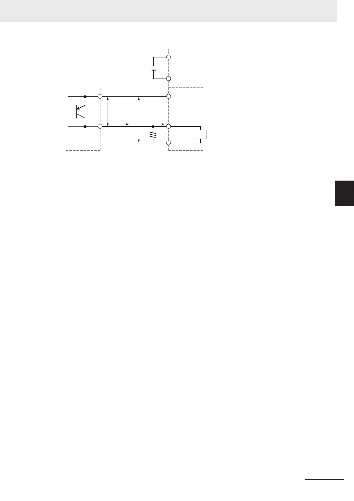
Two-wire sensor
High-speed Analog Input Unit
Unit that can supply I/O power
to the NX bus
V
CC
: Power supply voltage
V
R
: Sensor's output residual voltage
I
OUT
: Sensor control output (load current)
I
ON
: Input current at trigger input terminal of the High-speed Analog Input Unit (Input current when
the rated voltage is applied)
R: Bleeder resistor
Relation between OFF Current at Trigger Inputs and Sensor Leakage Cur-
rent
The trigger inputs of the High-speed Analog Input Units can detect sensor output OFF only when
the following conditions are satisfied:
I
OFF
≤
I
leak
When I
leak
is greater than I
OFF
, connect a bleeder resistor R.
Use the following equation to calculate the bleeder resistance constant.
R ≤ (V
OFF
/I
OFF
) × V
OFF
/(I
leak
× (V
OFF
/I
OFF
) - V
OFF
)
Use the following equation to calculate the rated power of a bleeder resistor.
Rated power W of bleeder resistor ≥ (V
CC
- V
R
)
2
/R × 4 [allowable margin]
The voltages and currents related to the conditions for NPN type sensors are shown in the figure
below.
4 Installation and Wiring
4 - 29
NX-series Analog I/O Units User’s Manual for High-speed Analog Input Units (W592)
4-4 Wiring External Devices
4
4-4-3 Precautions for Wiring