Setting Item Setting Value Description
Stop bit
• 1
(default)
• 2
1 or 2 bits appended to the end of the data per each charac-
ter to indicate End of the data.
Set it to match the communications specifications of the ex-
ternal device.
Data Bits
• 7
• 8
(default)
Length of the data bits. Select eight or seven.
Set it to match the communications specifications of the ex-
ternal device.
2 Set the Host Protocol as needed.
Set this when you wish to use RS-232C communications for control codes with an external de-
vice.
Behavior of the Host Protocol on page 4 - 5
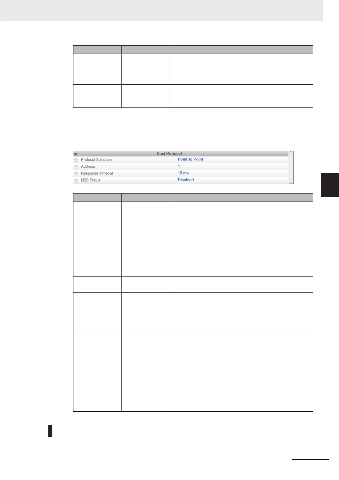
Setting Item Setting Value Description
Protocol Selection
• Point-to-Point
(default)
• Point-to-Point
with XOn/XOf
f
• ACK/NAK
• Polling Mode
• Point-to-Point: A basic RS-232C communication protocol
that does not control communication by a control code.
• Point-to-Point with XON/XOFF: RS-232C communication
protocol that performs data transfer control with the use of
XOn/XOff control codes.
• ACK/NAK: RS-232C communication protocol that per-
forms communication confirmation with the use of
ACK/NAK control codes.
• Polling Mode: Polling Mode is a protocol used in RS-422
communications. It is not used with the V430-F.
Address 1 to 50
(Default: 1)
The Polling Mode Address Number. It is not used with the
V430-F.
Response Timeout 0 to 255
(Default: 12)
Sets the Response Latency of the ACK/NAK Protocol (milli-
seconds). If the Response Timeout for the ACK/NAK re-
sponse to data transmission is being exceeded, the code
reader will cancel/release/clear the ACK/NAK Response Wait
State.
LRC Status
• Disabled
(Default)
• Enabled
When enabled, error checking to verify the accuracy of
RS-232C data transmission is added. Exclusive OR for all
characters following [STX] (beginning of text) up to [ETX]
(end of text). Cumulatively adds the binary sequence of all
characters to be transmitted. The result is that 1 is added
when the number of 1 is an odd number, and 0 is added
when the number is an even number. (0 is added in the case
of two instances of 1, or two instances of 0, while 1 is added
when there is only 0 or 1 instances) The data receiving side
executes the same operation and checks for errors by com-
paring with the LRC of the received data.
Behavior of the Host Protocol
Description of how each Host Protocol behaves
5 Controlling Operation and Data Output with RS-232C
5 - 5
V430-F Series Autofocus Multicode Reader User Manual for Communication Settings
5-1 Controlling Operation and Data Output with RS-232C
5
5-1-3 Communication Settings (Serial (RS-232C))

 Loading...

